

Description
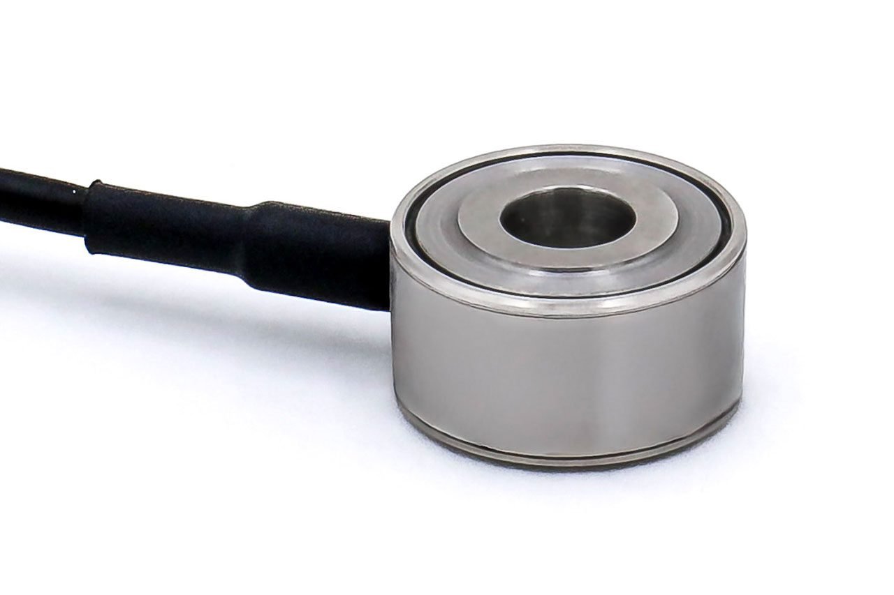
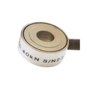
F207 Load Washer
Geometry: Axial strain cylinder in weather sealed case, with raised end load bearing faces and hole right through. For use in compression or in fail-safe tensile applications on a wide range of OEM or end-user applications.
The F207 is ideally suited to engineering force measurements where overall height is restricted; if a slight increase in height is acceptable the F313 may be a better choice.
It is designed for easy installation, usually between two flat faces bearing on its loading rings, either unattached or with retaining spigots positioned in the centre hole. Alternatively tensile load transfer can be achieved via a tie rod assembly through the centre hole. In this way the loadcell can indirectly measure tensile loads in a “fail-safe” mode.
We are happy to design variants of this loadcell to meet your specific requirements. Versions can be manufactured for fully compensated operation up to +250°C. Please consult our engineering department.
Specification
| Parameter | Value | Unit |
|---|---|---|
| Non-linearity – Terminal | ±2.0 (10kN) / ±2.0 (20 – 200kN) | % RL |
| Hysteresis | ±2.0 (10kN) / ±2.0 (20 – 200kN) | % RL |
| Creep – 20 minutes | ±0.1 (10kN) / ±0.1 (20 – 200kN) | % AL |
| Repeatability (valid for a fixed loadcell position with no rotation) | ±2.0 (10kN) / ±2.0 (20 – 200kN) | % RL |
| Rated output – Nominal | 1.3 (10kN) / 1.3 (20 – 200kN) | mV/V |
| Rated output – Rationalised | 1.0 (10kN) / 1.0 (20 – 200kN) | mV/V |
| Rationalisation tolerance | ±1.0 (10kN) / ±1.0 (20 – 200kN) | % RL |
| Zero load output | ±4 (10kN) / ±4 (20 – 200kN) | % RL |
| Temperature effect on rated output per °C | ±0.005 (10kN) / ±0.005 (20 – 200kN) | % AL |
| Temperature effect on zero load output per °C | ±0.03 (10kN) / ±0.03 (20 – 200kN) | % RL |
| Temperature range – Compensated | -10 to +50 (10kN) / -10 to +50 (20 – 200kN) | °C |
| Temperature range – Safe | -10 to +80 (10kN) / -10 to +80 (20 – 200kN) | °C |
| Excitation voltage – Recommended | 10 (10kN) / 10 (20 – 200kN) | V |
| Excitation voltage – Maximum | 10 (10kN) / 20 (20 – 200kN) | V |
| Bridge resistance | 350 (10kN) / 700 (20 – 200kN) | Ω |
| Insulation resistance – Minimum at 50Vdc | 500 (10kN) / 500 (20 – 200kN) | MΩ |
| Overload – Safe | 50 (10kN) / 50 (20 – 200kN) | % RL |
| Overload – Ultimate | 400 (10kN) / 400 (20 – 200kN) | % RL |
| Sealing | IP65 (10kN) / IP65 (20 – 200kN) | |
| Weight – Nominal (excluding cable) | 15 (10kN) / 20-260 (20 – 200kN) | g |
Order Codes
| Code | Description |
|---|---|
| F207CFR0K0 | Compression, IP65, unrationalised |
| F207CFR0KN | Compression, IP65, rationalised |
| Change the K to an H for the 1 tonnef range. |
Structural Stiffness
| Range (kN) | Stiffness (N/m) |
|---|---|
| 10 | 1.1 x 10⁹ |
| 20 | 2.2 x 10⁹ |
| 40 | 4.4 x 10⁹ |
| 80 | 8.8 x 10⁹ |
| 100 | 7.7 x 10⁹ |
| 120 | 7.1 x 10⁹ |
| 160 | 8.0 x 10⁹ |
| 200 | 1.0 x 10¹⁰ |
Notes
- AL = Applied load.
- RL = Rated load.
- Temperature coefficients apply over the compensated range.
- The load must be applied directly through the central loading axis.
Connections
For ranges up to 4 tonnefs the loadcell is fitted with 2 metres of PVC insulated 4 core screened cable type 7-1-4C. Ranges above 4 tonnefs are fitted with 7-2-4C cable.
Excitation + = Red, Excitation – = Blue, Signal + = Yellow, Signal – = Green, Screen = Orange.
The screen is not connected to the loadcell body.
When this loadcell is rationalised the resistors are housed in a capsule located in the loadcell cable 100mm from the free end. Capsule dimensions are Ø10mm by 57mm.
Reviews
There are no reviews yet.