

Description
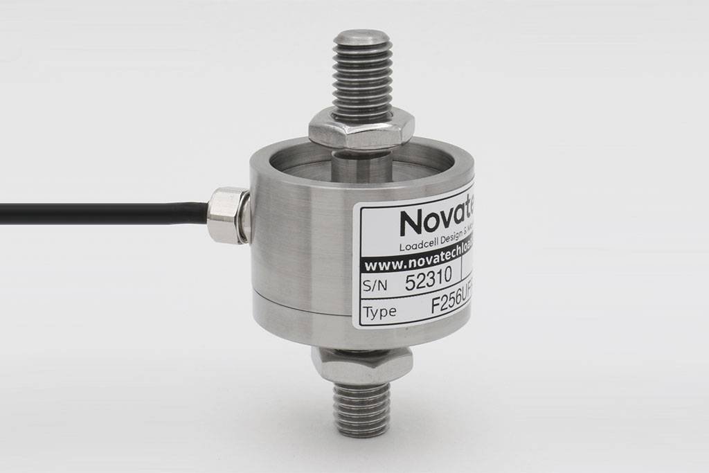
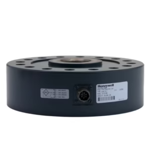
F256 Axial Compensated Loadcell
Geometry: Beam and diaphragm combination. Tension, compression and bi-directional options are available. All standard bi-directional loadcells are calibrated in both modes.
The loadcell’s unique strain system compensates for typical force misalignment in force measurement rigs and industrial weighing systems. Maximum error in axial force component measurement is limited to 0.25% within a 3° angle swept through 360° around the loadcell axis. Its various end fixing options are all inert and easily modified for direct inclusion in mechanical assemblies.
The basic versions are all sealed to IP65 with IP67 available as an option. See Engineering Application Sheet E032 and the ICA6H data-sheet for more information.
We are happy to design variants of this loadcell to meet your specific requirements. Versions can be manufactured for fully compensated operation up to +250°C. Please consult our engineering department.
A special version of the F256 loadcell widely used in Formula 1 racing is the Set-up wheel loadcell.
Specification
| Parameter | Value | Unit |
|---|---|---|
| Non-linearity – Terminal | ±0.05 | % RL |
| Hysteresis | ±0.05 | % RL |
| Creep – 20 minutes | ±0.05 | % AL |
| Repeatability | ±0.02 | % RL |
| Rated output – Rationalised | 2.0 | mV/V |
| Rationalisation tolerance (applies to single direction calibrations) | ±0.1 | % RL |
| Output symmetry | ±0.3 | %AO |
| Zero load output | ±4 | % RL |
| Temperature effect on rated output per °C | ±0.005 | % AL |
| Temperature effect on zero load output per °C | ±0.005 | % RL |
| Temperature range – Compensated | -10 to +50 | °C |
| Temperature range – Safe | -10 to +80 | °C |
| Excitation voltage – Recommended | 10 | V |
| Excitation voltage – Maximum | 20 | V |
| Bridge resistance | 700 | Ω |
| Insulation resistance – Minimum at 50Vdc | 500 | MΩ |
| Inclined load error – concentric at 3° | ±0.25 | % RL |
| Overload – Safe | 50 | % RL |
| Overload – Ultimate | 100 | % RL |
| Sealing – R option | IP65 | |
| Sealing – S option | IP67 | |
| Weight – Nominal (T version excluding cable) | 200-800N 0.1 | kg |
| 1.25-5kN 0.3 | kg | |
| 10-60kN 1.0 | kg |
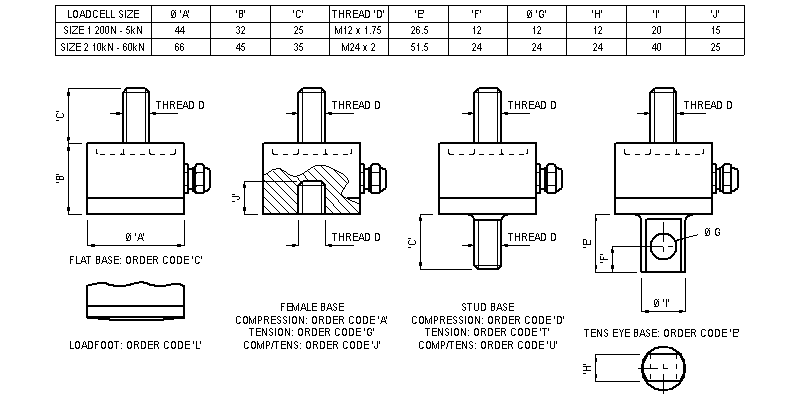
Order Codes
| Code | Description |
|---|---|
| F256CFR0KN | Compression, flat base, IP65 |
| F256LFR0KN | Compression, convex base, IP65 |
| F256TFR0KN | Tension, stud base, IP65 |
| F256DFR0KN | Compression, stud base, IP65 |
| F256UFR0KN | Bi-directional, stud base, IP65 |
| F256EFR0KN | Tension, eye base, IP65 |
| F256AFR0KN | Compression, female base, IP65 |
| F256GFR0KN | Tension, female base, IP65 |
| F256JFR0KN | Bi-directional, female base, IP65 |
| All F256s are rationalised as standard. Change R to an S for IP67. Integral amplifiers are not available with A, G or J options in the standard body height. We can manufacture specials with increased height if integral amplifiers are required. |
Structural Stiffness
| Range (kN) | Stiffness (N/m) |
|---|---|
| 200 (N) | 7.8 x 10⁶ |
| 400 (N) | 2.3 x 10⁷ |
| 800 (N) | 1.2 x 10⁷ |
| 1.25 | 1.9 x 10⁷ |
| 2.5 | 3.9 x 10⁷ |
| 5 | 7.8 x 10⁷ |
| 10 | 1.0 x 10⁸ |
| 20 | 2.0 x 10⁸ |
| 40 | 4.0 x 10⁸ |
| 60 | 6.0 x 10⁸ |
Notes
- AL = Applied load.
- RL = Rated load.
- Temperature coefficients apply over the compensated range.
- AO=Average of tension and compression outputs for full load.
Connections
For ranges up to 5kN the loadcell is fitted with 2 metres of PVC insulated 4 core screened cable type 7-2-4C. Ranges above 5kN are fitted with 16-2-4C cable.
Excitation + = Red, Excitation – = Blue, Signal + = Yellow, Signal – = Green, Screen = Orange.
Reverse the signal connections to obtain a positive signal in tension mode. The screen is not connected to the loadcell body.
Reviews
There are no reviews yet.