

Description
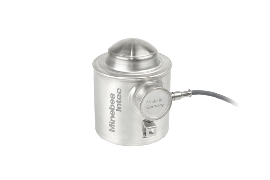
Compression load cell Inteco®, converter Connexx®, mounting kits PR 600x, PR 614x
The versatile, innovative weighing solution for silo and vessel weighing
The load cells of the Inteco® (PR 6203) series have been specially designed for weighing silos, tanks and process vessels. Their unique construction principle, in conjunction with the FlexLock mounting kits, makes it possible to compensate for lateral forces.
Unrivalled reliability, robustness and stability for your silo and process vessel weighing
- With maximum capacities from 500 kg to 75 t, accuracy classes from D1 to C6 and EX versions, almost all applications are possible.
- The pendulum support principle ensures there is always optimal force transmission into the sensor and thus minimises the influence on measuring accuracy, whilst also offering a large overload capacity, very high repeatability error and perfect linearity.
- With the FlexLock mounting kits, it is possible to compensate for movements arising from mechanical or thermal contraction or expansion of the container or the support structure.
- Thanks to the use of stainless steel in the housing and measuring elements and the top IP68/IP69 protection class, the cell holds its own even in adverse conditions.
Technical specifications
| Parameter | Description | Abbr. | PR 6203 D1/N | PR 6203 C3 | PR 6203 C6 | Unit |
| Accuracy class | 0.04 | 0.015 | 0.008 | %Emax | ||
| Minimum dead load | Lowest limit of specified measuring range | Emin | 0 | %Emax | ||
| Maximum capacity | Highest limit of specified measuring range | Emax | See Ordering information table | kg | ||
| Safe load limit | Maximum load without irreversible damage | Elim | For 500 kg … 50 t: 150
For 60 t: 125 For 75 t: 100 |
%Emax | ||
| Destructive load | Danger of mechanical destruction | Ed | For 500 kg … 50 t: >300
For 60 t: >250 For 75 t: >200 |
%Emax | ||
| Minimum LC verification | Minimum load cell verification interval (vmin = Emax/Y) | See Accuracy classes and minimum verification interval, vmin table | ||||
| For Emax = 500 kg | Y | 2,500 | n.a. | n.a. | ||
| For Emax = 1 t | Y | 5,000 | n.a. | n.a. | ||
| For Emax = 2 t | Y | 5,000 | 10,000 | n.a. | ||
| For Emax = 3 t … 75 t | Y | 5,000 | 14,000 | 3 t – 10 t:
14,000 ≥20 t: 20,000 |
||
| Deadload output return | Factor for deadload output return after load (DR=1/2*Emax/Z) | Z | 1,000 | 3,000 | 6,000 | |
| Rated output | Relative output at maximum capacity | Cn | 2 | 2 | 2 | mV/V |
| Tolerance on rated output | Permissible deviation from rated output | dc | <0.25 | <0.07 | <0.07 | %Cn |
| Zero output signal | Load cell output signal under unloaded condition | Smin | 0±1.0 | 0±1.0 | 0±1.0 | %Cn |
| Reproducibility | Max. change in load cell output for repeated loading | eR | 0.01 | 0.005 | 0.005 | %Cn |
| Creep | Max. change of output signal at Emax for 30 min. | dcr | <0.03 | <0.015 | <0.008 | %Cn |
| Non-linearity1) | Max. deviation from best straight line through zero | dLin | <0.03 | <0.01 | <0.01 | %Cn |
| Hysteresis1) | Max. difference in LC output between loading and unloading | dhy | <0.04 | <0.015 | <0.008 | %Cn |
| Temperature effect (TK) on Smin | Max. change of Smin in BT | TKSmin | <0.028 | <0.010 | <0.007 | %Cn/10 K |
| Temperature effect (TK) on parameter1) | Max. change of C in BT | TKC | <0.03 | <0.010 | <0.005 | %Cn/10 K |
| Input impedance | Between supply terminals | RLC | 650 ±6 | 650 ±6 | 650 ±6 | Ω |
| Output impedance | Between measuring terminals | RO | 610 ±1 | 610 ±0.5 | 610 ±0.5 | Ω |
| For Emax = 60 t | RO | 510 ±1 | 510 ±0.5 | 510 ±0.5 | Ω | |
| For Emax = 75 t | RO | 410 ±1 | 410 ±0.5 | 410 ±0.5 | Ω | |
| Insulation impedance | Between measuring circuit and housing at 100 VDC | RIS | >5,000 × 106 | Ω | ||
| Insulation voltage | Between circuit and housing (Inteco® only) | 500 | V | |||
| Recommended supply voltage | To hold the specified performance | Bu | 4…24 | VDC | ||
| Max. supply voltage | Permissible for continuous operation without dam- age | Umax | 32 (Ex versions: 25) | VDC | ||
| Nominal ambient temp. range | To hold the specified performance | BT | -10 … +40 | -10 … +40 | -10 … +40 | °C |
| Usable temperature range | Permissible for continuous operation without dam- age | BTu | -40 … +95 | -40 … +95 | -40 … +95 | °C |
| Storage temperature range | Without electrical and mechanical stress | BTi | -40 … +95 | -40 … +95 | -40 … +95 | °C |
| Material (load cell housing) | Stainless steel 1.4301 acc. DIN EN 10088-3 (conforms to 304 AISI) | |||||
| Permissible eccentricity | Permissible displacement from nominal load line | Sex | For 500 kg … 10 t: 10
For 20 t … 75 t: 5 |
mm | ||
| Vibration resistance | Resistance against oscillations (IEC 68-2-6 Fc) | 20 g, 100 h, 10 … 150 Hz | ||||
1) The data for non-linearity (dLin), hysteresis (dhy) and temperature effect on C (TKC) are typical values. For OIML R60 or NTEP approved load cells, the sum of these values is within the permissible cumulative error limits.
| Parameter | Description | Abbr. | PR 6203 D1/N | PR 6203 C3 | PR 6203 C6 | Unit |
| Barometric pressure influence | Influence of barometric pressure on output | PKSmin | 500 kg … 3 t: 200
5 t … 10 t: 330 20 t … 75 t: 420 |
g/kPa | ||
| Nominal deflection | Max. elastic deformation under maximum capacity | Snom | ≤5 t: ≤0.3/≤20 t: ≤0.5/≤50 t: ≤0.8/ 60 t … 75 t: ≤1.2 | mm | ||
| Protection class | according to IEC 529
– Inteco: IP66 / IP68* / IP69 – Connexx®: IP66 / IP 68** |
|||||
| Cable | Length: Emax ≤10 t: 5 m, Emax >10 t: 12 m Diameter: 5 mm
Cross section: 4 × 0.35 mm2 Material cable sheath: TPE |
|||||
| Bending radius | ≥25 mm in case of fixed installation
≥75 mm in case of flexible installation |
|||||
| Connexx® | ||||
| Nominal ambient temp. range | To hold the specified performance | BT | -10 … +40 | °C |
| Usable temperature range | Permissible for continuous operation without dam- age | BTu | -30 … +60 | °C |
| Storage temperature range | Without electrical and mechanical stress | BTi | -30 … +70 | °C |
* The load cell can be submerged in water at a depth of 1.5 m for 10,000 hours.
** The module can be submerged in water at a depth of 1.5 m for 100 hours.
| Accuracy classes and minimum verification interval, vmin | |||||||||
| OIML | NTEP Class III Multiple | NTEP Class IIIL Multiple | |||||||
| D1/D1E | C3/C3E | C6/C6E | D1/D1E | C3/C3E | C6/C6E | D1/D1E | C3/C3E | C6/C6E | |
| Maximum number of verification intervals, nmax | 1,000 | 3,000 | 6,000 | 1,000 | 5,000 | 10,000 | 2,000 | 10,000 | 10,000 |
| 500 kg | 0.2 kg | n.a. | n.a. | 0.2 kg | n.a. | n.a. | n.a. | n.a. | n.a. |
| 1 t | 0.2 kg | n.a. | n.a. | 0.2 kg | n.a. | n.a. | n.a. | n.a. | n.a. |
| 2 t | 0.4 kg | 0.2 kg | n.a. | 0.4 kg | 0.2 kg | n.a. | 0.2 kg | 0.2 kg | n.a. |
| 3 t | 0.6 kg | 0.22 kg | 0.22 kg | 0.6 kg | 0.22 kg | 0.22 kg | 0.2 kg | 0.2 kg | 0.2 kg |
| 5 t | 1 kg | 0.36 kg | 0.36 kg | 1 kg | 0.36 kg | 0.36 kg | 0.34 kg | 0.2 kg | 0.2 kg |
| 10 t | 2 kg | 0.72 kg | 0.72 kg | 2 kg | 0.72 kg | 0.72 kg | 0.67 kg | 0.24 kg | 0.24 kg |
| 20 t | 4 kg | 1.43 kg | 1 kg | 4 kg | 1.43 kg | 1 kg | 1.34 kg | 0.48 kg | 0.34 kg |
| 30 t | 6 kg | 2.15 kg | 1.5 kg | 6 kg | 2.15 kg | 1.5 kg | 2 kg | 0.72 kg | 0.5 kg |
| 50 t | 10 kg | 3.58 kg | 2.5 kg | 10 kg | 3.58 kg | 2.5 kg | 3.34 kg | 1.2 kg | 0.84 kg |
| 60 t | 12 kg | 4.29 kg | 3 kg | 12 kg | 4.29 kg | 3 kg | 4 kg | 1.43 kg | 1 kg |
| 75 t | 15 kg | 5.36 kg | 3.75 kg | 15 kg | 5.36 kg | 3.75 kg | 5 kg | 1.79 kg | 1.25 kg |
Time savings with matched output
The output impedance (R0) and parameter (Cn) of the load cells are within a tight tolerance range(= matched output) both individually and together. A preliminary adjustment of the entire measure- ment chain can therefore be performed without reference weight. Thanks to the matched output technology, a damaged load cell can be replaced without the need for recalibration.
Reviews
There are no reviews yet.