

Description
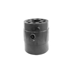
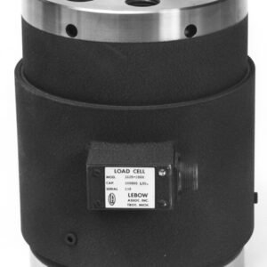
Compression load cell PR 6201 and mounting kits PR 6001, PR 614x
The high-load weighing solution for silo and vessel weighing
The load cell from the PR 6201 series has been specially designed for high-load weighing of silos and tanks. Its unique construction principle, in conjunction with the FlexLock mounting kits, makes it possible to compensate for movements with a negligible effect on the weighing result.
Unrivalled reliability, robustness and stability for your silo weighing
- For unusually large and heavy silos with maximum capacities from 100 t to 520 t.
- With the FlexLock mounting kits, it is possible to compensate for movements arising from mechanical or thermal contraction or expansion of the container or the support structure.
- Thanks to the use of stainless steel and the top IP68/ IP69 protection class, the cell holds its own even in adverse conditions.
- For maximum capacities of 500 kg to 200 t, a direct 4…20 mA analogue output is optionally available.
Technical specifications
Compression load cell PR 6201 (0.5 t–50 t)
| Parameter | Description | Abbr. | 0,5 t – 50 t | 100 t – 520 t | Unit | |||||
| LA | LA | L | 520 t L | N | ||||||
| Accuracy class | 0.25 | 0.5 | 0.5 | 0.5 | 0.06 | %Emax | ||||
| Minimum dead load | Lowest limit of specified measuring range | Emin | 0 | %Emax | ||||||
| Maximum capacity | Highest limit of specified measuring range | Emax | See Ordering information table | kg | ||||||
| Safe load limit | Maximum load without irreversible damage | Elim | For 0,5 t … 30 t:
For 50 t: |
200
150 |
For 100 t, 200 t:
For 300 t: For 520 t: |
200
133 106 |
%Emax | |||
| Destructive load | Danger of mechanical d estruction | Ed | For 0,5 t … 30 t:
For 50 t: |
>500
>300 |
For 100 t, 200 t:
For 300 t: For 520 t: |
>500
>333 >192 |
%Emax | |||
| Minimum LC verification Interval | Minimum verification interval, vmin = Emax/Y | Y | / | / | ||||||
| Deadload output return | Factor for deadload output return after load (DR=1/2*Emax/Z) | Z Z | /
/ |
/
/ |
||||||
| Rated output | Relative output at maximum capac- ity (LA = 4 … 20 mA)
For Emax = 50 t |
Cn
Cn |
16 mA
16 mA |
16 mA | 1 | 2.6 | 1.0/
300 t = 1.5 |
mV/V
mV/V |
||
| Tolerance on rated output | Permissible deviation from rated output | dc | <1.0 | <1.0 | <1.0 | <1.0 | <0.25 | %Cn | ||
| Zero output signal | Load cell output signal under unloaded condition | Smin | 4 mA* | 4 mA | <2.0 | <2.0 | <1.0 | %Cn | ||
| Reproducibility | Max. change in load cell output for repeated loading | eR | <0.02 | <0.02 | <0.02 | <0.02 | <0.01 | %Cn | ||
| Creep | Max. change of output signal at Emax for 30 min. | dcr | <0.05 | <0.05 | <0.05 | <0.2 | <0.03 | %Cn | ||
| Non-linearity | Max. deviation from best straight line through zero | dLin | <0.25 | <0.3 | <0.3 | <0.1 | <0.05 | %Cn | ||
| Hysteresis | Max. difference in LC output between loading and unloading | dhy | <0.25 | <0.25 | <0.25 | <0.5 | <0.06/ 100 t:
<0.04 |
%Cn | ||
| Temperature effect (TK) on Smin | Max. change of Smin in BT | TKSmin | <0.15 | <0.2 | <0.2 | <0.2 | <0.06 | %Cn/10 K | ||
| Temperature effect (TK) on parameter | Max. change of C in BT | TKC | <0.1 | <0.1 | <0.1 | <0.1 | <0.03 | %Cn/10 K | ||
| Input impedance | Between supply terminals | RLC | / | / | 650 +50 | 650 +50 | 650 ±6 | Ω | ||
| Output impedance | Between supply terminals | RO | / | / | 610 ±3 | 610 ±3 | 610 ±1 | Ω | ||
| Insulation impedance | Between measuring circuit and housing at 100 VDC | RIS | / | / | >5,000 × 106 | Ω | ||||
| Insulation voltage | Between circuit and housing (PR 62../..E only) | / | / | 500 | V | |||||
| Recommended supply voltage | To hold the specified performance | Bu | 20 … 28 | 20…28 | 4…24 | VDC | ||||
| Max. supply voltage | Permissible for continuous operation without damage | Umax | 28 | 28 | 32 (Ex versions: 25) | VDC | ||||
| Nominal ambient temp. range | To hold the specified performance | BT | -10 … +55 | -10 …
+55 |
-10 … +55 | °C | ||||
| Usable temperature range | Permissible for continuous operation without damage | BTu | -30 … +55 | -30 …
+55 |
-40 … +95 | °C | ||||
| Storage temperature range | Without electrical and mechanical stress | BTi | -40 … +70 | -40 …
+70 |
-40 … +95 | °C | ||||
| Permissible eccentricity | Permissible displacement from nom- inal load line | Sex | For 0,5 t … 10 t:
For 20 t … 50 t: |
10
5 |
10 | mm | ||||
| Vibration resistance | Resistance against oscillations (IEC 68-2-6 Fc) | 20 g, 100 h, 10 … 150 Hz | ||||||||
| Barometric pressure influence | Influence of barometric pressure on output | PKSmin | Up to 2 t: 280
3 t to 10 t: 320 From 20 t: 420 |
100 t: 700
200 t, 300 t, 520 t: 1,400 |
g/kPa | |||||
| Nominal deflection | Max. elastic deformation under maximum capacity | Snom | Up to 30 t ≤0.5/50 t
≤0.8 |
100 t: 1.0/200 t: 1.6/300 t: 2.4/520 t: 2.7 | mm | |||||
| Parameter | Description | Abbr. | 0,5 t – 50 t | 100 t – 520 t | Unit | |||
| LA | LA | L | 520 t L | N | ||||
| Material
(load cell housing) |
Stainless steel 1.4301 acc. DIN EN 10088-3 (conforms to 304 AISI/SAE) | |||||||
| Protection class | IP66 / IP68 / IP69 | |||||||
| Cable | Length: Emax ≤10 t: 5 m, Emax >10 t: 12 m Diameter: 5 mm
Cross section: 4 × 0.35 mm2 Material cable sheath: TPE |
|||||||
| Bending radius | ≥25 mm in case of fixed installation
≥75 mm in case of flexible installation |
|||||||
* Zero output signal tolerance: -2 ± 2%Cn, i.e. 3.36 mA… 4.00 mA
Mounting kits PR 6001
| Maximum capa- city of load cell PR 6201 |
Mounting kit/ accessories |
Material |
Description/ comments |
Mounting screws (not included in delivery) | Installation height (mm) | Max. permissible horizontal force (kN) | Max. permissible lift-off force (kN) | Max. permissible eccentricity | Max. permissible vertical load with- out load cell | Max. permissible load for jack-up | CE approval according to EN 1090 |
|
100 t |
PR 6001/02N | Steel electrogalva- nised, chromated and sealed (RoHS com- pliant) | Mounting disc incl. upper load disc | M16-8.8 | 290 | / | 40 |
± 5 |
38 t |
/ | Yes |
| PR 6001/32N | High-load mounting kit incl. upper load disc | M20-8.8 | 350 | 200 | 250 | / | Yes | ||||
| 200 t –
300 t |
PR 6001/03N | Steel electrogalva- nised, chromated and sealed (RoHS com- pliant) | Mounting disc incl. upper load disc | M20-8.8 | 385 | / | 50 |
± 5 |
54 t |
/ | Yes |
| PR 6001/33N | High-load mounting kit incl. upper load disc | M20-8.8 | 445 | 200 | 250 | / | Yes |
Mounting kits PR 6143
| Maximum capa- city of load cell PR 6201 |
Mounting kit/ accessories |
Material |
Description/ comments |
Mounting screws (not included in delivery) |
Installation height (mm) |
Max. permissible horizontal force (kN) | Max. permissi- ble lift-off force (kN)** | CE approval according to EN 1090 |
|
100 t |
PR 6143/15N |
Steel electrogalvanised, chromated and sealed (RoHS compliant) |
MiniFLEXLOCK incl. upper load disc |
M20-8.8 |
290 |
150 |
200 |
Yes |
| 200 t –
300 t |
PR 6143/25N |
Steel electrogalvanised, chromated and sealed (RoHS compliant) |
MiniFLEXLOCK incl. upper load disc |
M20-8.8 |
385 |
150 |
200 |
Yes |
|
520 t |
PR 6143/55N |
Steel electrogalvanised, chromated and sealed (RoHS compliant) |
Upper load disc and base |
/ |
/ |
/ |
/ |
/ |
* Lower load disc only for 0.5 t–10 t, for 20 t–75 t please order base PR 6143/54S separately
** With separate threaded bolt of strength class 8.8 or A2-70
Mounting kits PR 6144
| Maximum capa- city of load cell PR 6201 |
Mounting kit/ accessories |
Material |
Description/ comments |
Mounting screws (not included in delivery) |
Installation height (mm) |
Max. permissible horizontal force (kN) |
Max. permissible lift-off force (kN) |
Max. permissible vertical load with- out load cell | CE approval according to EN 1090 |
|
100 t |
PR 6144/15N |
Steel electrogalvanised, chromated and sealed (RoHS compliant) |
Seismic Mount incl. load cell dummy |
M30-8.8 |
298 |
440 |
600 |
24 t |
Yes |
| 200 t –
300 t |
PR 6144/35N |
M36-8.8 |
385 |
520 |
880 |
60 t |
Yes |
||
|
520 t |
PR 6144/55N |
428 |
520 |
880 |
110 t |
Yes |
Mounting kits PR 6145
| Maximum capa- city of load cell PR 6201 |
Mounting kit/ accessories |
Material |
Description/ comments |
Mounting screws (not included in delivery) |
Installation height (mm) |
CE approval according to EN 1090 |
|
100 t |
PR 6145/08N |
Steel electrogalvanised, chromated and sealed (RoHS compliant) |
Plate mounting kit incl. upper load disc |
M16-8.8 |
290 |
Yes |
| 200 t –
300 t |
PR 6145/10N |
Steel electrogalvanised, chromated and sealed (RoHS compliant) |
Plate mounting kit incl. upper load disc |
M20-8.8 |
385 |
Yes |
Fixed bearing PR 6101
| Maximum capa- city of load cell PR 6201 |
Fixed bearing |
Material |
Mounting screws (not included in delivery) |
Installation height (mm) |
Max. usable load |
Permissible hori- zontal force for usable load (kN) |
|
100 t |
PR 6101/15N |
Steel electrogalvanised, chromated and sealed (RoHS compliant) |
M16-8.8 |
290 |
100 t | 200 |
| 200 t | 120 | |||||
| 200 t –
300 t |
PR 6101/25N |
Steel electrogalvanised, chromated and sealed (RoHS compliant) |
M20-8.8 |
385 |
200 t | 350 |
| 300 t | 300 | |||||
| 400 t | 180 | |||||
|
520 t |
PR 6101/55N |
Steel electrogalvanised, chromated and sealed (RoHS compliant) |
M36-8.8 |
428 |
520 t | 390 |
| 550 t | 340 |
You can find the mounting kits for PR 6201/500 kg – 50 t LA in the data sheet for the Inteco® compression load cell.
Technical diagrams
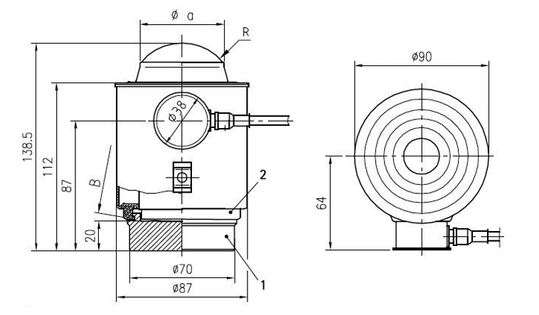
Load cells PR 6201
| Pos. | Designation |
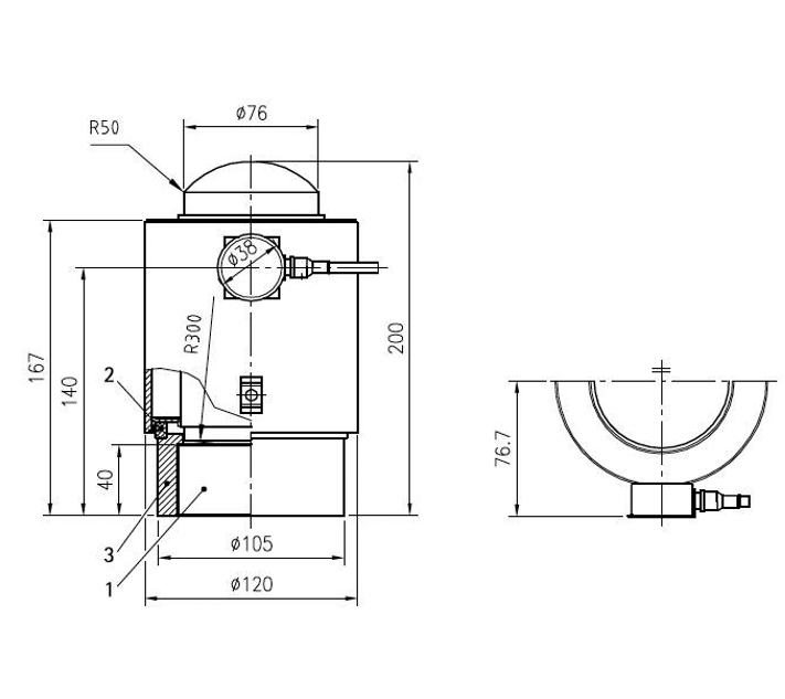
| 1 | Lower load disc |
| 2 | Support ring |
| 3 | Ring for lower load disc |
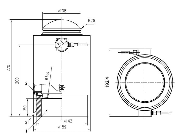
Load cell PR 6201/15 (maximum capacity 100 t)
| Pos. | Designation |
| 1 | Lower load disc |
| 2 | Support ring |
| 3 | Ring for lower load disc |
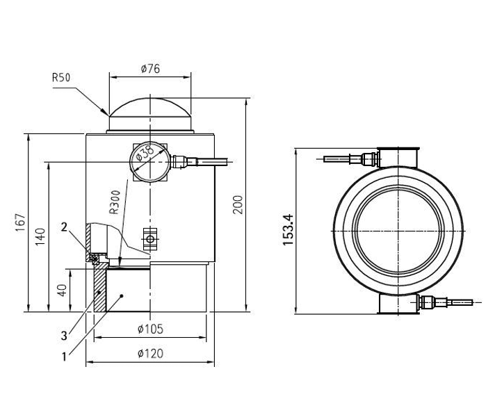
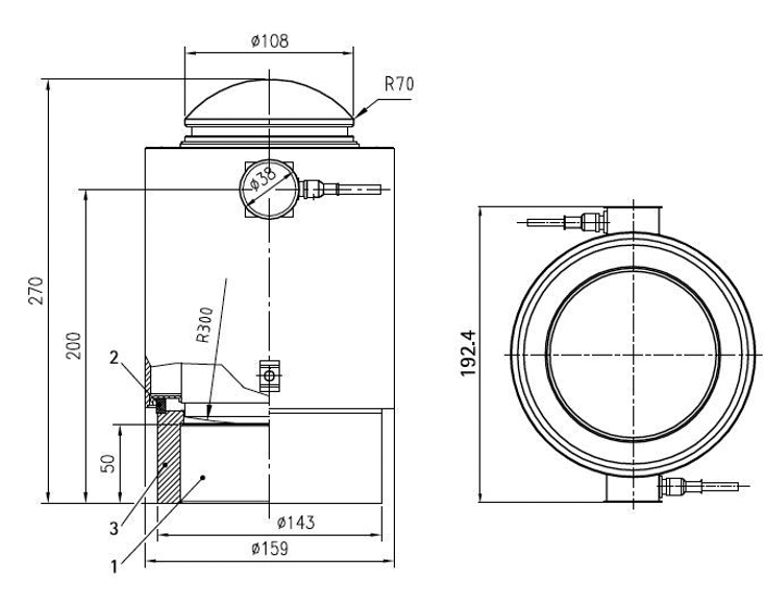
Load cell PR 6201/15 DB (maximum capacity 100 t)
| Pos. | Designation |
| 1 | Lower load disc |
| 2 | Support ring |
| 3 | Ring for lower load disc |
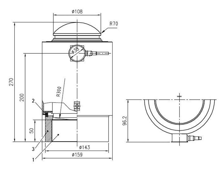
Load cell PR 6201/25 (maximum capacity 200 t), PR 6201/35 (maximum capacity 300 t)
| Pos. | Designation |
| 1 | Lower load disc |
| 2 | Support ring |
| 3 | Ring for lower load disc |
Load cell PR 6201/25 (maximum capacity 200 t), PR 6201/35 (maximum capacity 300 t)
| Pos. | Designation |
| 1 | Lower load disc |
| 2 | Support ring |
| 3 | Ring for lower load disc |
Load cell PR 6201/25 DB (maximum capacity 200 t), PR 6201/35 DB (maximum capacity 300 t)
| Pos. | Designation |
| 1 | Lower load disc |
| 2 | Support ring |
| Model | Ø a | R | B |
| PR 6201/52 … 23 | 24 | 15 | 150 |
| PR 6201/33 … 14 | 34 | 15 | 150 |
| PR 6201/24 … 54 | 56 | 35 | 220 |
Reviews
There are no reviews yet.