

Description
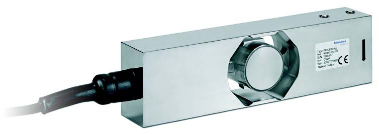
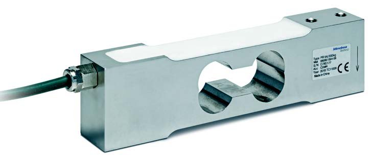
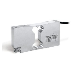
Single Point load cells PR 53 and PR 54
Precise measuring results for scale construction and a wide range of industrial applications.
With the LC series Single Point load cells, you can rely on the tried-and-tested quality of a leading manufacturer of industrial weighing technology. The stainless steel Single Point load cells PR 53 and PR 54 are available for loads ranging from 7.5 kg to 200 kg and a platform size of up to 500 mm x 400 mm.
Verifiable load cells for a variety of industrial applications
- These load cells, developed in Germany, guarantee the most accurate weighing results. All load cells are verifiable according to OIML R60 and NTEP.
- The PR 53 and PR 54 cover a load spectrum from 7.5 kg/10 kg to 200 kg. Stainless steel ensures a long product lifetime.
- A comprehensive optional portfolio of transmitters, indicators and controllers ensures reliable continuous processing of the measurement signals as desired.
- Comprehensive expertise in scale production ensures high-quality advice for individual projects.
| Single Point load cells PR 53 and PR 54 | |||||
| Parameter | Description | Abbr. | PR 53 C3MR | PR 54 C3MR | Unit |
| Accuracy class | 0.02 | % Emax | |||
| Minimum dead load | Lowest limit of specified measuring range | Emin | 0 | % Emax | |
| Maximum capacity | Highest limit of specified measuring range | Emax | 10, 15, 20, 30, 50, 100 | 7.5, 10, 15, 20, 30, 50, 100, 200 | kg |
| Maximum usable load | Upper limit for measurements | Elim | 150 | % Emax | |
| Destructive load | Danger of mechanical destruction | Ed | 300 | % Emax | |
| Minimum LC verification | Minimum load cell scale interval, vmin = Emax/Y | Y | 15000 | ||
| Deadload output return | Factor for deadload output return after load (DR = 1/2*Emax /Z) | Z | 3000 | ||
| Rated output | Relative output at maximum capacity | Cn | 2 | mV/V | |
| Tolerance on rated output | Permissible deviation from rated output | dc | < 10 | %Cn | |
| Zero output signal | Load cell output signal under unloaded condition | Smin | 0 ± 5 | %Cn | |
| Repeatability error | Max. change in load cell output for repeated loading | eR | < 0.01 | %Cn | |
| Creep | Max. change of output signal at Emax during 30 min. | dcr | < 0.0166 | %Cn | |
| Non-linearity1) | Deviation from best straight line through zero | dLin | < 0.0166 (200 kg: < 0.0233 | < 0.0166 | %Cn |
| Hysteresis1) | Max. difference in LC output between loading and unloading | dhy | < 0.0166 | %Cn | |
| Temperature effect (TK) on Smin | Max. change related to Cn of Smin per 10 K in BT | TKSmin | < 0.0093 | %Cn/10 K | |
| TK of the parameter C1) | Max. change related to Cn of C per 10K in BT | TKC | < 0.0117 | %Cn/10 K | |
| Off-centre load error | 0.0233 | %Cn | |||
| Input impedance | Between supply terminals | RLC | 380 ± 38 | Ω | |
| Output impedance | Between measuring terminals | RO | 350 ± 25 | Ω | |
| Insulation impedance | Between measuring circuit and housing at 100 VDC | RIS | >5,000 × 106 | Ω | |
| Nominal supply voltage range | To hold the specified performance | Bu | ≤ 12 | VDC | |
| Max. supply voltage | Continuous operation without damage | Umax | 15 | VDC | |
| Nominal ambient temp. range | To hold the specified performance | BT | -10 to +40 | °C | |
| Usable ambient temp. range | Continuous operation without damage | BTu | -30 to +70 | -20 to +65 | °C |
| Storage temperature range | Without electrical and mechanical stress | BTi | -50 to +80 | -25 to +70 | °C |
| Barometric pressure influence | Influence of barometric pressure on output | < 0.00667 | %Cn | ||
| Nominal deflection | Max. elastic deformation under maximum capacity | Snom | < 0.3 | < 0.5 | mm |
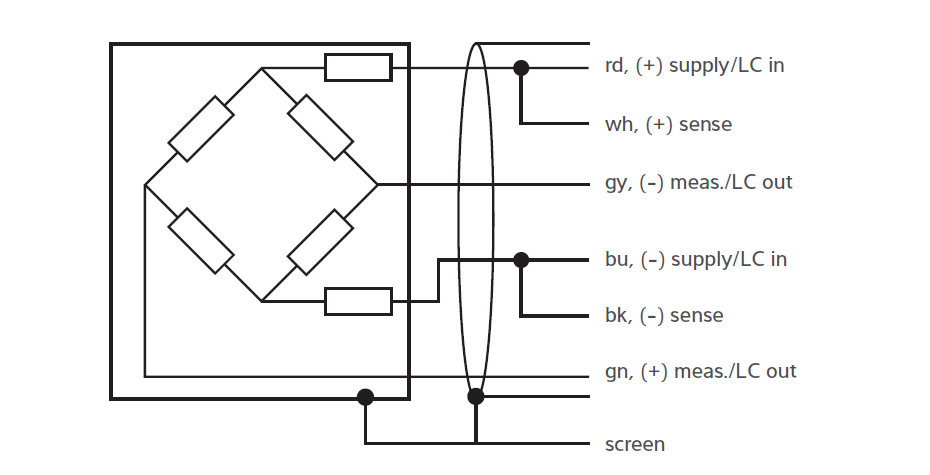
| Cable length | 3.5 | 3 | m | ||
| Material | Stainless steel 1.4545 (DIN EN 10088-3) | ||||
| Max. platform size | In compliance with the technical data according to OIML R76 | 500 × 400 | mm × mm | ||
| IP protection class | According to EN 60529 | IP66/IP68/IP69 | IP66/IP67 | ||
1)Non-linearity (dLin), hysteresis (dhy) and parameter temperature effect (TKC) are typical values. For OIML R60- and NTEP-approved load cells, the total of these values is within the permitted cumulative error limits.
| Accuracy classes and minimum scale interval, vmin | ||||||||||
| Maximum number of scale intervals, nmax | 7.5 kg | 10 kg | 15 kg | 20 kg | 30 kg | 50 kg | 100 kg | 200 kg | Unit | |
| OIML R60 C3MR | 3000 | 0.5 | 0.67 | 1.00 | 1.34 | 2.00 | 3.34 | 6.67 | 13.34 | g |
| NTEP Class III Single | 5000 | 0.5 | 0.67 | 1.00 | 1.34 | 2.00 | 3.34 | 6.67 | 13.34 | g |
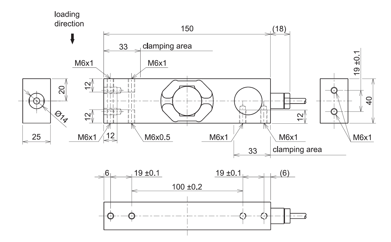
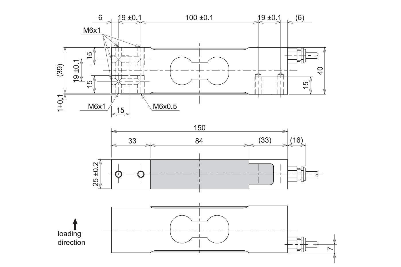
All dimensions in mm
Ex approval Scope of validity:
Single Point load cell LC stainless steel
| Zone | Marking | Certificate number | For |
| 0 and 1 | II 1G Ex ia IIC T6/T4 Ga | BVS 21 ATEX E 023 X IECEx BVS 21.0024X | Only PR 5x/xx E |
| 20 | II 1D Ex ia IIIC T₂₀₀ 165°C Da | ||
| 2 | II 3G Ex ec IIC T6/T4 Gc | All PR 5x without E | |
| 21 | II 2D Ex tb IIIC T110°C Db |
| Single Point load cells PR 53 | |
| Model | Order number |
| PR 53/10 kg C3MR | 9409 253 07010 |
| PR 53/15 kg C3MR | 9409 253 07015 |
| PR 53/20 kg C3MR | 9409 253 07020 |
| PR 53/30 kg C3MR | 9409 253 07030 |
| PR 53/50 kg C3MR | 9409 253 07050 |
| PR 53/100 kg C3MR | 9409 253 07110 |
| Single Point load cells PR 54 | |
| Model | Order number |
| PR 54/7.5 kg C3MR | 9409 254 07007 |
| PR 54/10 kg C3MR | 9409 254 07010 |
| PR 54/15 kg C3MR | 9409 254 07015 |
| PR 54/20 kg C3MR | 9409 254 07020 |
| PR 54/30 kg C3MR | 9409 254 07030 |
| PR 54/50 kg C3MR | 9409 254 07050 |
| PR 54/100 kg C3MR | 9409 254 07110 |
| PR 54/200 kg C3MR | 9409 254 07120 |
| Single Point load cells NTEP and EX PR 53 | |
| Model | Order number |
| PR 53/xx kg III 5000 S | 9409 253 0Cxx |
| PR 53/xx kg C3MRE | 9409 653 07xxx |
| Single Point load cells NTEP and EX PR 54 | |
| Model | Order number |
| PR 54/xx kg III 5000 S | 9409 254 0Cxxx |
| PR 54/xx kg C3MRE | 9409 654 07xxx |


Reviews
There are no reviews yet.