

Description
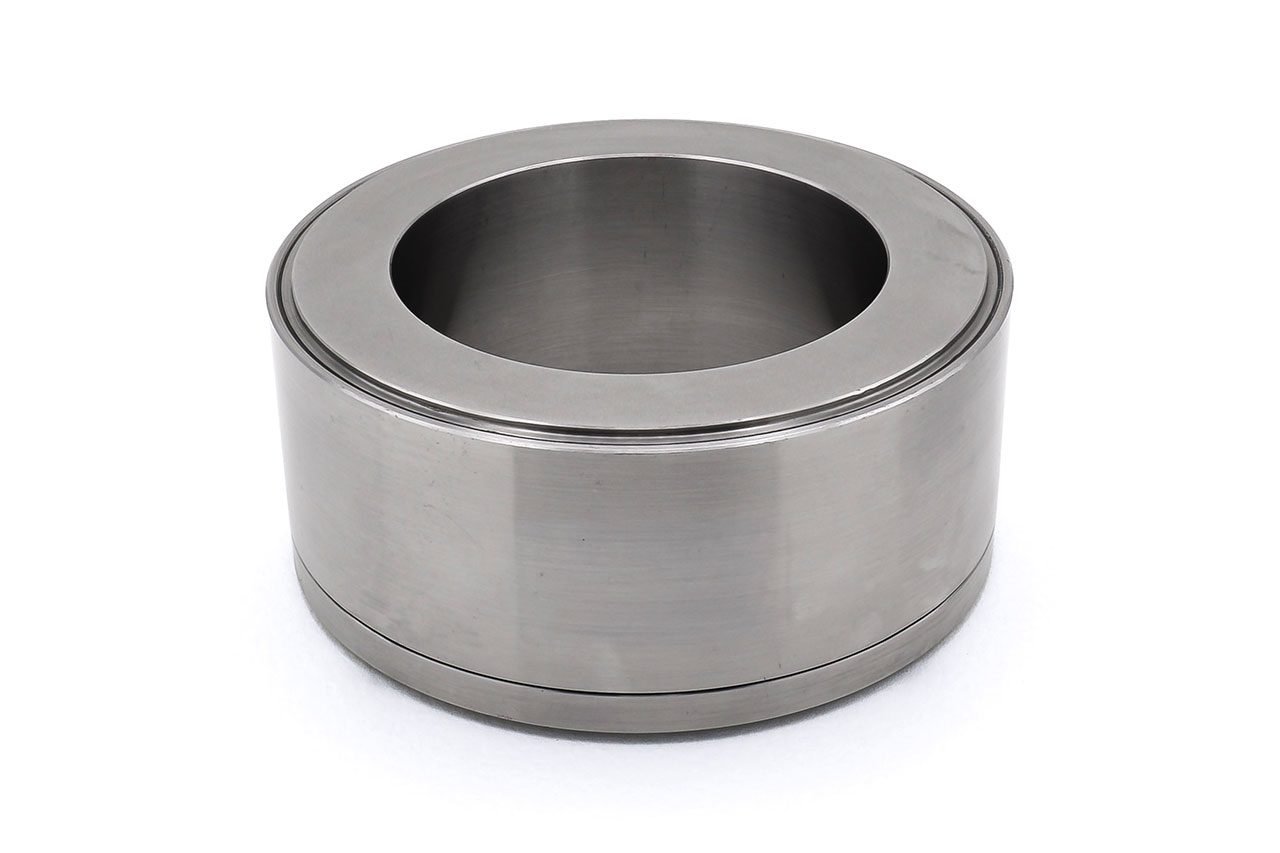
F209 Donut Loadcell
F209 Donut Loadcell. Geometry: Axial strain cylinder in a sealed case, with raised end load bearing faces and hole right through. For use in compression or in fail-safe tensile applications.
The F209 is ideally suited to engineering force measurements including through centre safety testing of cables, rods and bolts.
It is designed for easy installation, usually between two flat faces bearing on its loading rings, either unattached or with retaining spigots positioned in the centre hole. Alternatively tensile load transfer can be achieved via a tie rod assembly through the centre hole. In this way the loadcell can indirectly measure tensile loads in a “fail-safe” mode.
We are happy to design variants of this loadcell to meet your specific requirements. Please consult our engineering department.
Specification
| Parameter | Value | Unit |
|---|---|---|
| Non-linearity – Terminal | ±1.0 | % RL |
| Hysteresis | ±1.0 | % RL |
| Creep – 20 minutes | ±0.1 | % AL |
| Repeatability | ±0.02 | % RL |
| Rated output – Nominal | 1.2 | mV/V |
| Rated output – Rationalised (1000 and 2000kN) | 1.0 | mV/V |
| Rationalisation tolerance | ±0.5 | % RL |
| Zero load output | ±4 | % RL |
| Temperature effect on rated output per °C | ±0.005 | % AL |
| Temperature effect on zero load output per °C | ±0.03 | % RL |
| Temperature range – Compensated | -10 to +50 | °C |
| Temperature range – Safe | -10 to +80 | °C |
| Excitation voltage – Recommended | 10 | V |
| Excitation voltage – Maximum | 10 | V |
| Bridge resistance | 350 | Ω |
| Insulation resistance – Minimum at 50Vdc | 500 | MΩ |
| Overload – Safe | 50 | % RL |
| Overload – Ultimate | 400 | % RL |
| Sealing | IP65 | |
| Weight – Nominal (excluding cable) | 7 to 9 | kg |
Order Codes
| Code | Description |
|---|---|
| F209CFR0H0 | Compression, IP65, unrationalised |
| F209CFR0HN | Compression, IP65, rationalised |
| Change the F to a P for the connector version. |
Structural Stiffness
| Range (kN) | Stiffness (N/m) |
|---|---|
| 1000 | 4.0 x 10¹⁰ |
| 2000 | 8.0 x 10¹⁰ |
| 4000 | 1.6 x 10¹¹ |
Notes
- AL = Applied load.
- RL = Rated load.
- Temperature coefficients apply over the compensated range.
- The load must be applied directly through the central loading axis.
Connections
The loadcell is fitted with 2 metres of PVC insulated 4 core screened cable type 16-2-4C or a 4 pin Binder 723 series chassis plug.
Excitation + = Red or pin 1, Excitation – = Blue or pin 2, Signal + = Yellow or pin 3, Signal – = Green or pin 4, Screen = Orange.
The screen is not connected to the loadcell body.

Reviews
There are no reviews yet.