

Description
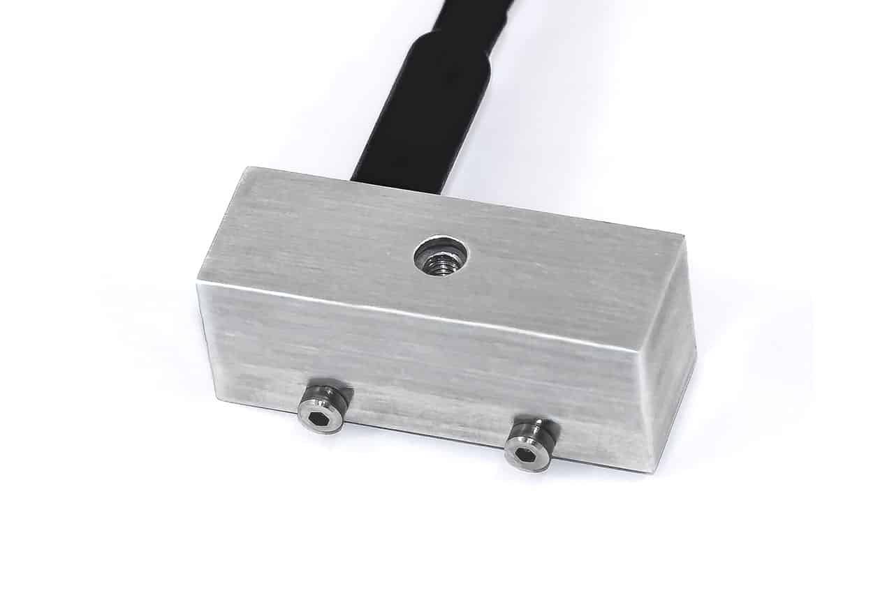
F332 2 Axis Loadcell
The loadcell is ideally suited to many industrial and scientific applications, including medical research and biometrics.
The recessed input fixing removes the possibility of applying any force to the delicate strain system during transport, storage or general handling. The design of the case is such that there is a degree of in-built overload protection during normal use. Input torque to the live force input fixing must be minimal, normal frictional torques achieving thread insertion should not be exceeded i.e. thread locking by adhesive is suggested.
If large moment arms are present the performance specification may be affected. It is best to contact members of our engineering department, who will be happy to evaluate performance changes. The loadcell can be manufactured with dimensions, fixings and force ranges to suit the application. Please consult our engineering department about the viability of all required design changes.
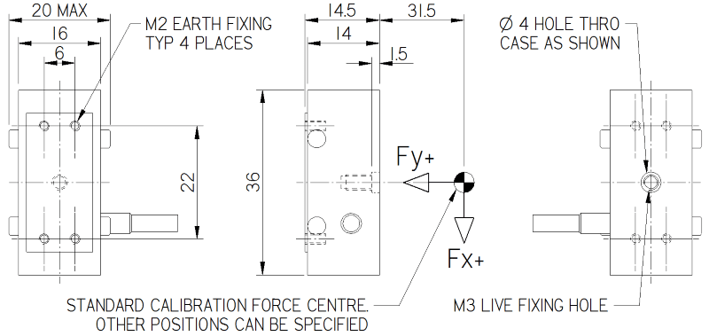
The example shown in the picture and drawing is a 0.1N (10gf) model; there may be some small enforced differences in the dimensions or fixings for custom force ranges.
We are always happy to design variants of this or any other standard loadcell product to meet your specific requirements.
Additional information on specifying a multi-axis loadcell can be found in Engineering Sheet E015.
The loadcell is ideally suited to many industrial and scientific applications, including medical research and biometrics.
The recessed input fixing removes the possibility of applying any force to the delicate strain system during transport, storage or general handling. The design of the case is such that there is a degree of in-built overload protection during normal use. Input torque to the live force input fixing must be minimal, normal frictional torques achieving thread insertion should not be exceeded i.e. thread locking by adhesive is suggested.
If large moment arms are present the performance specification may be affected. It is best to contact members of our engineering department, who will be happy to evaluate performance changes. The loadcell can be manufactured with dimensions, fixings and force ranges to suit the application. Please consult our engineering department about the viability of all required design changes.
The example shown in the picture and drawing is a 0.1N (10gf) model; there may be some small enforced differences in the dimensions or fixings for custom force ranges.
We are always happy to design variants of this or any other standard loadcell product to meet your specific requirements.
Additional information on specifying a multi-axis loadcell can be found in Engineering Sheet E015.
Specification
| Parameter | Value | Unit |
|---|---|---|
| Non-linearity – Terminal | ±0.5 | % RL |
| Hysteresis | ±0.5 | % RL |
| Creep – 20 minutes | ±0.5 | % AL |
| Repeatability | ±0.2 | % RL |
| Maximum cross talk | 3 | % RL |
| Rated output – Nominal | 0.2 to 1.2 | mV/V |
| Zero load output | ±10 | % RL |
| Temperature effect on rated output per °C | ±0.005 | % AL |
| Temperature effect on zero load output per °C | ±0.01 to ±0.05 | % RL |
| Temperature range – Compensated | -10 to +50 | °C |
| Temperature range – Safe | -10 to +80 | °C |
| Excitation voltage – Recommended | 5 | V |
| Excitation voltage – Maximum | 10 | V |
| Bridge resistance | 2500 | Ω |
| Insulation resistance – Minimum at 50Vdc | 500 | MΩ |
| Overload – Safe | 50 | % RL |
| Weight – Nominal (excluding cable) | 10 to 40 | g |
Structural Stiffness
| Range (kN) | Stiffness (N/m) |
|---|---|
| 0.1 (per axis) | 1 x 10⁴ |
| 10 (per axis) | 1 x 10⁶ |
| 50 (per axis) | 5 x 10⁶ |
| 100 (per axis) | 1 x 10⁷ |
Notes
- AL = Applied load.
- RL = Rated load.
- Temperature coefficients apply over the compensated range.
- Values apply to all axes unless otherwise specified.
Connections
| The F332 is fitted with 2 metres of PVC insulated 9 core screened cable type 7-1-9C. The screen is not connected to the loadcell body. |
| Function | Wire Colour | |
|---|---|---|
| X axis | Y axis | |
| Excitation + | Red | Violet |
| Excitation – | Blue | Black |
| Signal + | Yellow | Brown |
| Signal – | Green | White |
| Screen | Orange (thick) | |


Reviews
There are no reviews yet.