

Description
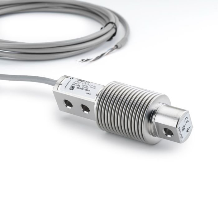
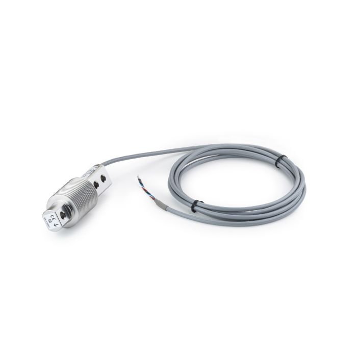
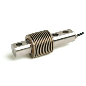
SENSiQ® Shear Beam Load Cell VBB / VEB 5 … 500 kg
Application
VBB-type load cells convert proportionally the mechanical input variable force into the electrical variable voltage.
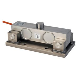
When used in conjunction with the corresponding VEB elastomer bearings, they are ideal for use in platform scales, dosing scales, and container scales. The compact
design facilitates planning into any given construction.
The robustness of the load cells and bearings ensures reliable operation even in harsh environmental conditions.
Construction
The VBB load cells are entirely made of stainless steel and hermetically sealed through laser welding. They are connected electrically by a high-quality, 6-wire screened
PVC cable.
The six-wire circuitry makes the measuring signal insensitive to differences in lengths of the connection cables.
Function
▪ High calibration accuracy which provides ideal conditions for the parallel arrangement of load cells
▪ High reproducibility of the measuring signals
▪ Damping of dynamic lateral loads as a result of the elastomer mount
▪ Self-centering after transverse loading
▪ Extremely small measured value influence as a result of lateral forces
Dimension
Load cells VBB 5 kg – 0.5 t
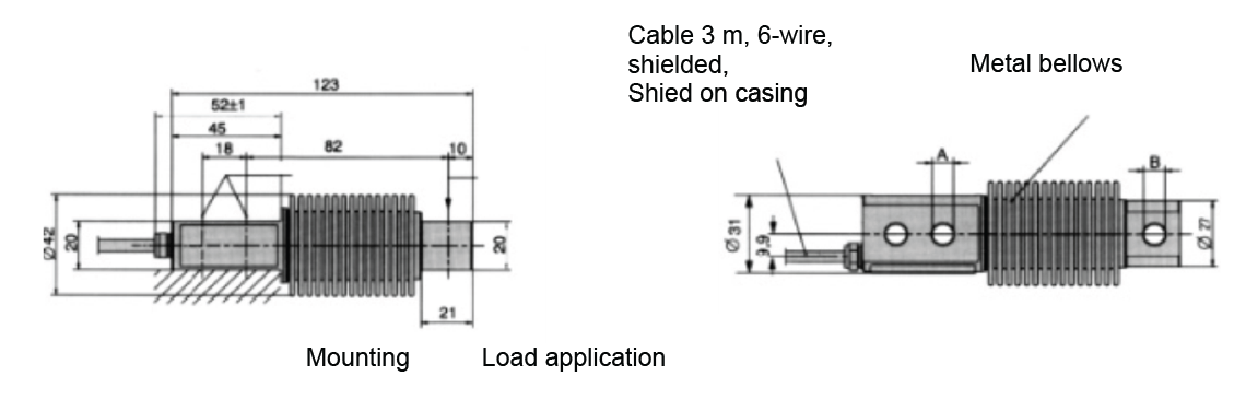
| Model | Dimensions A [mm] | Dimensions B [mm] |
| VBB 5 kg – 0.2 t | 8.2 | 8.2 |
| VBB 0.5 t | 10.5 | 11.1 |
Elastomer mount VEB 5 kg – 0.5 t for VBB load cells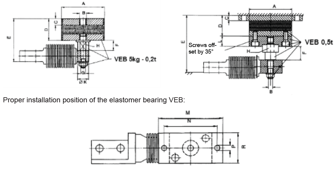
| Elastomer mount | A | G | C | D | E | F | G | H | K | L | M | N | P | R | FR* | Smax** |
| VEB 5 kg – 0.2 t | 75 | M12 | 12 | 40 | 79 ±1.3 | 18.5 | M8 | AWI 17 | 19 | – | – | – | – | – | 163 | 3 |
| VEB 0.5 t | 80 | M10 | 10 | 39 | 105+2.1/-2.2 | 26 | – | AWI 27 | – | 20 | 120 | 100 | 9 | 60 | 400 | 4.5 |
* Restoring force FR in N, at 1 mm lateral displacement
** maximum allowable lateral displacement Smax in mm, at rated load.
Technical Data
| Nominal load | Emax | 5 kg – 0.5 t | – | ||||||
| Accuracy class | – | D1 | C3* | C4* | C6*** | Ref | |||
| Nominal characteristic value | Cn | 2 mV/V +20 μV/V; -2 μV/V | 2 mV/V ±1 μV/V | – | |||||
| Compound error | Fcomb | 0.05 % | 0.02 % | 0.013 % | 0.01 % | Cn | |||
| Return to zero signal after load (30 min) | Fdr | ±0.049 % | ±0.016 % | ±0.012 % | ±0.008 % | Cn | |||
| Creepage under load (30 min) | Fcr | ±0.049 % | ±0.016 % | ±0.012 % | ±0.008 % | Cn | |||
| Temperature coefficient of the zero sig- nal | TK0 | ±0.05 %/10 K | ±0.0125 %/10 K | ±0.009 %/10 K | ±0.009 %/10 K | Cn в Вtn | |||
| Temperature coefficient of the charac- teristic value | TKc | ±0.05 %/10 K | ±0.008 %/10 K | ±0.007 %/10 K | ±0.004 %/10 K | Cn в Вtn | |||
| max. admissible no. of legal-for-trade scale intervals | nLC | 1000 | 3000 | 4000 | 6000 | – | |||
| Smallest scale interval | Vmin | 0.036 % | 0.009 % | 0.0066 % | 0.0066 % | Еmax | |||
| Minimum application range | Bamin | 36 % | 27 % | 26 % | 39 % | Еmax | |||
| max. application range | Bamax | Bamax = Emax | – | ||||||
| Input resistance | Re | 350 Ω – 480 Ω | tr | ||||||
| Output resistance | Ra | 356 Ω ±0.2 Ω | 356 Ω ±0.12 Ω | tr | |||||
| Zero Signal | S0 | ±1 % | Cn | ||||||
| Max. supply voltage | Usmax | 18 V | – | ||||||
| Nominal temperature | Btn | -10 °C … +40 °C | – | ||||||
| Operating temperature range | Btu | -40 °C … +70 °C | – | ||||||
| Operating temperature range explosion-proof design | – | -30 °C … +70 °C (ATEX, IECEx, EAC) -30 °C … +40 °C (FM-Approval Canada and USA) |
– | ||||||
| Reference temperature | tr | 23 °C | – | ||||||
| Storage temperature range | Bts | -50 °C … +85 °C | – | ||||||
| Limit load | EL | 150 % | Cn | ||||||
| Breaking load | ED | 300 % | Cn | ||||||
| Measuring path **** for nominal load | – | 0.25 mm 5 kg |
0.3 mm 10 – 100 kg |
0.4 mm 200 kg |
0.6 mm 500 kg |
– | |||
| Type of protection | – | IP68 (enhanced test conditions: 1 m water column; 100 h) | – | ||||||
| Type of protection Explosion-proof design | – | IP67 | – | ||||||
| Cable specification | – | PVC cable, length 3 m, 6 wires, shielded, shield on casing | – | ||||||
| Connection assignment | – | black: Input- / blue: Input+ / black/yellow: Shield / red: Output- / white: Out- put+ / gray: Sensor- / green: Sensor+ | – | ||||||
| Corrosion protection | – | Stainless steel | – | ||||||
* Quality C3 is only available for rated loads > 10 kg
** Quality C4 is only available for rated loads > 20 kg
*** Quality C6 is only available for rated loads > 50 kg
**** Overload stops should be set at (measuring range + 0.05 mm) when the scale is unloaded.
Option explosion-proof approvals
| Intrinsically safe explosion-proof design: Option 2GD | Non-intrinsically safe explosion-proof design: Option 2D, 3G | |
| ATEX / IECEx | II 2G Ex ia IIC T4 Gb (Zone 1) II 2D Ex ia IIIC T125°C Db, IP67 (Zone 21) |
II 3G Ex ec IIC T4 Gc (Zone 2) II 2D Ex tb IIIC T125 °C Db, IP67 (Zone 21) |
| FM-Approval Kanada | I / 0 / Ex ia / IIC / T4; -30°C < Ta < 40°C / Ga; 20 / Ex ia / IIIC / T125°C; -30°C < Ta < 40°C / Da; IP67. |
not available |
| FM-Approval USA | IS / I, II, III / 1 / A, B, C, D, E, F, G / T4; -30°C < Ta < 40°C, I / 0 / AEx ia / IIC / T4; -30°C < Ta < 40°C / Ga; 20 / AEx ia / IIIC / T125°C; -30°C < Ta < 40°C / Da; IP67. |
not available |
| EAC | 1Ex ia IIC T4 Gb (Zone 1) Ex ia IIIC T125°C Dc X (Zone 22) |
2Ex nA II T4 Gc (Zone 2) Ex tc IIIC T125 °C Dc X (Zone 22) |
Load cells marked as intrinsically safe (Ex “i”) are operated in an intrinsically safe manner regardless of the zone.
CAUTION! The verification of intrinsically safe circuit must be verified. New barriers are provided in particular for new systems. Verifications of intrinsic safety are available for all load cells and barriers.
Order Numbers
| Design of load cells | Order Number | Ex-design of load cells | Order number option 2GD | Order number option 2D, 3G |
| VBB 5 kg D1 | D 725 417.01 | – | – | – |
| VBB 10 kg D1 | D 725 417.02 | – | – | – |
| VBB 10 kg СЗ | D 725 419.02 | VBB 10 kg СЗ “Ex” | D 725 419.32 | D 725 419.42 |
| VBB 20 kg D1 | D 725 417.03 | – | – | – |
| VBB 20 kg C3 | D 725 419.03 | VBB 20 kg C3 “Ex” | D 725 419.33 | D 725 419.43 |
| VBB 50 kg D1 | D 725 417.04 | – | – | – |
| VBB 50 kg C3 | D 725 419.04 | VBB 50 kg C3 “Ex” | D 725 419.34 | D 725 419.44 |
| VBB 0.1 t D1 | D 725 409.01 | VBB 0.1 t D1 “Ex” | D 725 409.61 | D 725 409.41 |
| VBB 0.1 t C3 | D 725 409.04 | VBB 0.1 t C3 “Ex” | D 725 409.64 | D 725 409.44 |
| VBB 0.1 t C4 | D 726 370.01 | VBB 0.1 t C4 “Ex” | D 726 370.31 | D 726 370.41 |
| VBB 0.2 t D1 | D 725 409.02 | VBB 0.2 t D1 “Ex” | D 725 409.62 | D 725 409.42 |
| VBB 0.2 t C3 | D 725 409.05 | VBB 0.2 t C3 “Ex” | D 725 409.65 | D 725 409.45 |
| VBB 0.2 t C4 | D 726 370.02 | VBB 0.2 t C4 “Ex” | D 726 370.32 | D 726 370.42 |
| VBB 0.2 t C6 | D 726 370.04 | VBB 0.2 t C6 “Ex” | D 726 370.34 | D 726 370.44 |
| VBB 0.5 t D1 | D 725 409.03 | VBB 0.5 t D1 “Ex” | D 725 409.63 | D 725 409.43 |
| VBB 0.5 t C3 | D 725 409.06 | VBB 0.5 t C3 “Ex” | D 725 409.66 | D 725 409.46 |
| VBB 0.5 t C4 | D 726 370.03 | VBB 0.5 t C4 “Ex” | D 726 370.33 | D 726 370.43 |
| Elastomer mount description | Purchase Order Number | Elastomer mount description | Order Number |
| VEB 5 kg – 0.2 t | D 725 408.01 | VEB 0.5 t | D 725 408.02 |
Order example:
Rated load 0.2 t, Precision class C6: Typ VBB 0.2 t C6 – Order number D 726 370.04 Other models on request.

Reviews
There are no reviews yet.