

Description
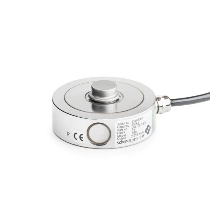
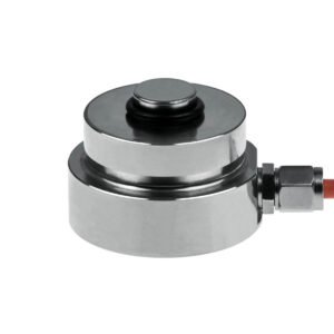
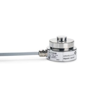
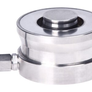
RTB Ring Torsion Load Cell
More Information
| RTB 0,25 t C3 | RTB 0,5 t C3 | RTB 0,25t C3 MR | RTB 0,50 t MR | |
| SKU | VP4225901 | VP4226101 | VP4226001 | VP4226201 |
| Order number | V041086.B01 | V041087.B01 | V041086.B07 | V041087.B07 |
| Weight [kg] | 1 | 1.05 | 0.83 | 1 |
| HS-Code | 8423 90 10 | 8423 90 10 | 8423 90 10 | 9031 80 20 |
| Estimated Delivery Time [Weeks] | 28 | 28 | 28 | 28 |
| Accuracy | C3 | C3 | C3 | C3 |
| Capacity [t] | 0.25 | 0.5 | 0.25 | 0.25 |
| ATEX-Category | None | None | None | None |
| Product Family | SENSiQ Loadcell RTB | SENSiQ Loadcell RTB | SENSiQ Loadcell RTB | SENSiQ Loadcell RTB |
Application
The load cell as transducer converts the mechanical input variable force proportionally into the electronic output variable voltage.
The specific model of the ring torsion load cell offers the user specific advantages:
• The extremely small frame size simplifies the use in almost all weighing device applications.
• The robust construction allows problem-free transport, installation and operation, also under rough ambient conditions (disturbance forces, temperature).
Design
• Hermetically sealed encapsulation through laser welding and glass-metal implementation (IP68)
• Corrosion protection through the use of stainless steel
• All electrical components are located inside the load cell and thus are optimally protected.
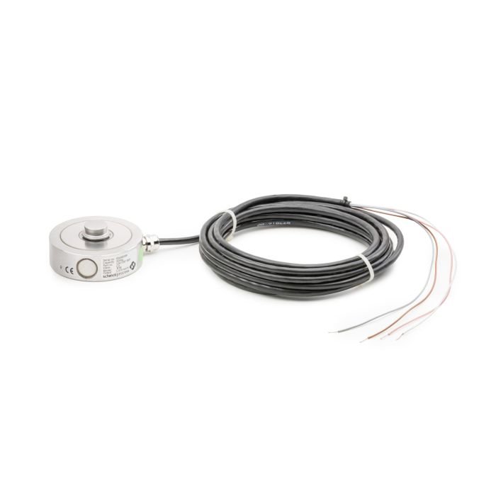
• The high quality and robust connecting cable is guided radially into the load cell.
• Mechanically compatible with the RTK type series
• Hermetically sealed encapsulation through laser welding and glass-metal implementation (IP68)
• Corrosion protection through the use of stainless steel
• All electrical components are located inside the load cell and thus are optimally protected.
• The high quality and robust connecting cable is guided radially into the load cell.
• Mechanically compatible with the RTK type series
Function
• High reproducibility
• High long-term stability and therefore consistently high accuracy permanently
• Extremely small measured value influence as a result of lateral forces
• High functional safety, even with frequently unavoidable impact loads and constraining forces, as well as with electrical interferences
• Torque-free force input/output as a result of the direct, vertical power train
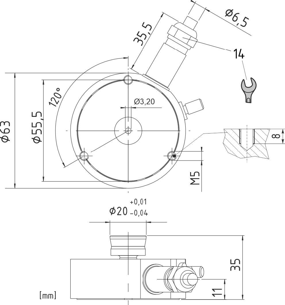
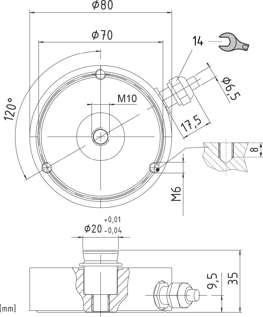
Dimension
| RTB 0.13 t | RTB 0.25 t / 0.5 t |
 |
 |
Technical Data
| Nominal load | Emax | 0.13 t | 0.25 t | 0.5 t | 0.5 t | – |
| Accuracy class | C3 | C3 | C3 | C5 | Ref | |
| Nominal characteristic value | Cn | 1 mV/V ±0.1 mV/V |
1.75 mV/V 2 mV/V |
±0.2 mV/V ±0.1 mV/V |
2 mV/V ±0.1 mV/V |
– |
| Compound error | Fcomb | ±0.023 % | ±0.023 % | ±0.014 % | Cn | |
| Return to zero signal after load (30 min) | Fdr | ±0.0167 % | ±0.0167 % | ±0.0083 % | Cn | |
| Creepage under load (30 min) | Fcr | ±0.012 % | ±0.0245 % | ±0.0123 % | Cn, Btn | |
| Hysteresis | – | ±0.017 % | ±0.0167 % | ±0.0083 % | Cn, Btn | |
| Temperature coefficient of the zero signal per 10 K | TK0 | ±0.008 % – |
±0.014 % ±0.007 % |
±0.009 % ±0.009 % |
Cn, Btn Option MR |
|
| Temperature coefficient of the characteristic value per 10 K | TKc | ±0.008 % | ±0.01 % | ±0.005 % | Cn, Btn | |
| Max. allowed number of verifi- able division values | nLC | 3000 | 3000 | 5000 | – | |
| Smallest scale interval | Vmin | Emax/17500 – |
Emax/10000 Emax/20000 |
Emax/17500 Emax/17500 |
Standard Option MR |
|
| Minimum application range | Bamin | 17 % – |
30 % 15 % |
40 % | Emax Option MR |
|
| Max. application range | Bamax | 100 % | Emax | |||
| Maximum capacity * | Ll | 150 % | Emax | |||
| Max. lateral load ** | Lq | 20 % | Emax | |||
| Input resistance | Re | 1260 Ω ±100 Ω | 1100 Ω ±100 Ω | 1100 Ω ±100 Ω | 1100 Ω ±100 Ω | – |
| Output resistance | Ra | 1020 Ω ±0.5 Ω | 1025 Ω ±25 Ω | 1025 Ω ±25 Ω | 1025 Ω ±25 Ω | – |
| Zero Signal | S0 | 1 % | 1.5 % | 1 % | 1 % | Cn |
| Supply voltage | Us | max. 30 V (recommended: 5 V – 15 V) | – | |||
| Nominal temperature | Btn | -10 °C … +40 °C | – | |||
| Operating temperature range | Btu | -30 °C … +70 °C | -35 °C … +70 °C | -35 °C … +70 °C | -35 °C … +70 °C | – |
| Storage temperature range | – | -50 °C … +90 °C | – | |||
| Type of protection | – | IP68 | – | |||
| Cable specification – Cable length 5 m, shield insulated from housing (0.13 t) or connected to –housing (0.25 0.50 t) | ||||||
| Connection assignment | – | Input +82: pink / Input -81: gray Output +28: brown / Output -27: white |
– | |||
| Material | – | Stainless steel | – | |||
| Corrosion protection | – | see resistance table DDP8 483 | – | |||
| Recommended tightening torque for the fastening bolts | – | 8 N m | 12 … 14 N m | 12 … 14 N m | 12 … 14 N m | – |
* Permissible vibration stress according to DIN 50100: 70 % Emax; peak loading values may not exceed Emax.
** In combination with elastomer bearings, SEM must be observed that the reset force of the elastomer bearings already represents a transverse force.
ATEX approval
| Only operate intrinsically safely | II 1G Ex ia IIC T4 Ga II 1D Ex ia IIIC T73°C Da |
| Not operated intrinsically safely | II 3G Ex nA IIC T4 Gc II 3D Ex tc IIIC T63°C Dc |
Order numbers
| Version [t] | Accuracy class C3 | Accuracy class C5 |
| 0.13 | V041085.B01 | – |
| 0.25 | V041086.B01 | – |
| 0.50 | V041087.B01 | V041087.B05 |
| 0.25 MR | V041086.B07 | – |
| 0.50 MR | V041087.B07 | – |
| Order numbers ATEX/IECEX version
II 1G Ex ia IIC T4 Ga / II 1D Ex ia IIIC T73°C Da / II 3G Ex nA IIC T4 Gc / II 3D Ex tc IIIC T63°C Dc * |
||
| 0.13 | V041085.B11 | — |
| 0.25 | V041086.B11 | — |
| 0.50 | V041087.B11 | V041087.B15 |
* Tick the appropriate box on the type plate to indicate whether the load cell is used in the 1GD or 3GD area. For category 1GD or 2GD, the load cell must be connected intrinsically safe.
Installation accessories
- SENSiQ Secure Mount SSM
- SENSiQ Elastomer Mount SEM
Reviews
There are no reviews yet.