

Description
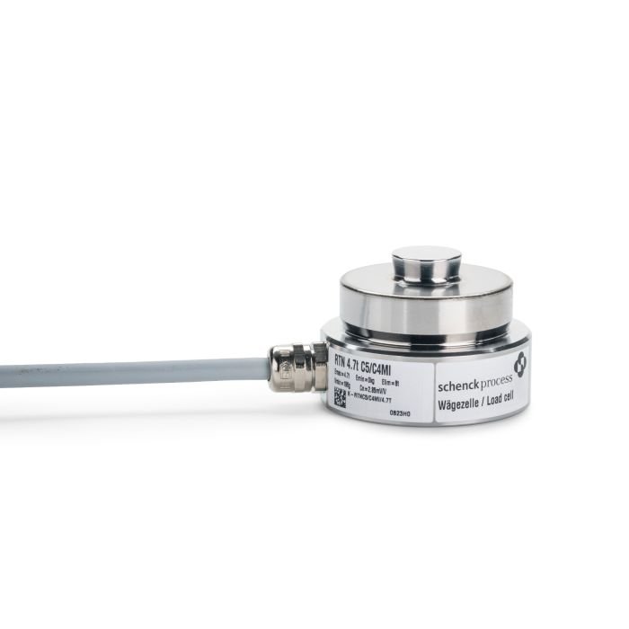
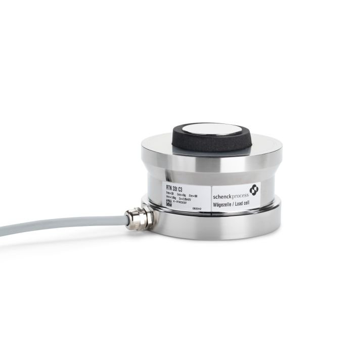
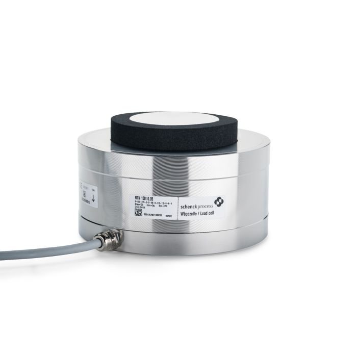
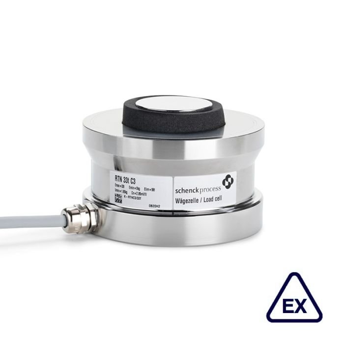
Ring Torsion Load Cell RTN 1 t …470 t
Application
As a measuring transducer, the load cell converts the mechanical input variable ‘force’ proportionally into the electrical output variable ‘voltage’.
The consistent optimization of the ring torsion load cell offers the user specific advantages:
▪ The extremely small frame size simplifies the use in almost all weighing device applications
▪ The durable design allows easy transportation, installation and operation, even in very rough ambient conditions (disturbing forces, temperature)
Construction
▪ Hermetically sealed encapsulation through laser welding(IP68)
▪ High corrosion protection thanks to electrolytically polished stainless steel
▪ All electrical components are located inside the load cell and thus are optimally protected
▪ The high quality and robust connecting cable is guided radially into the load cell
▪ In combination with adapter kits, the RTN load cells are compatible with former designs.
Function
▪ High measuring sensitivity
▪ High reproducibility
▪ High long-term stability and therefore consistently high accuracy permanently
▪ Extremely small measured value influence as a result of lateral forces
▪ High functional safety, even with frequently unavoidable impact loads and constraining forces, as well as with electrical interferences
▪ Integrated overvoltage protection
▪ Torque-free force input/output as a result of the direct, vertical power train
▪ Plug variants for fast and inexpensive replacement of damaged cables
Dimensions and basic data
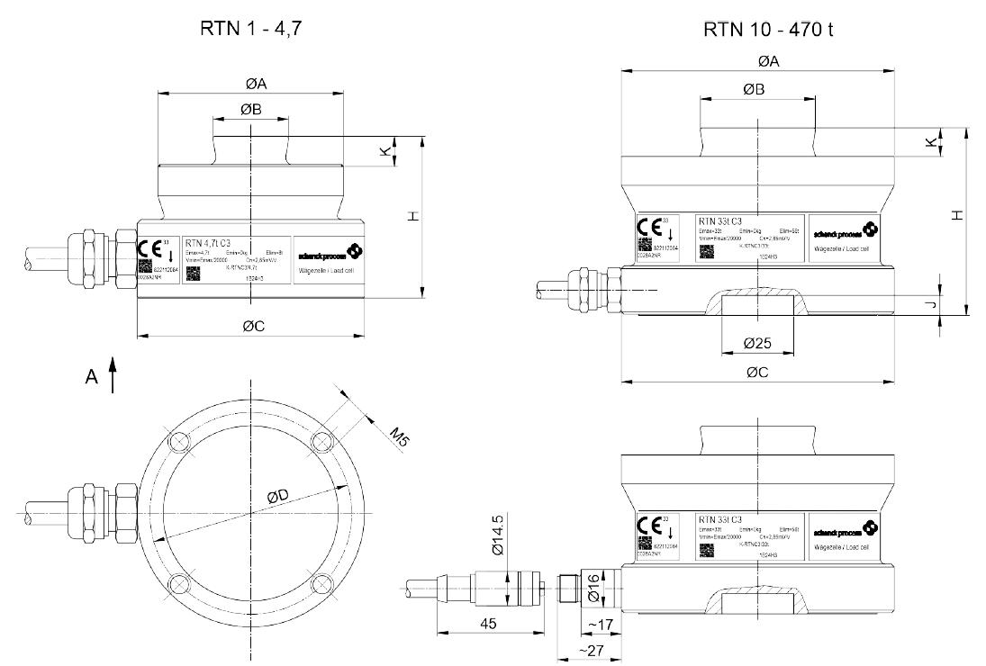
View A
| RTN(Type) | A(mm) | B(mm) | C(mm) | D(mm) | H(mm) | K(mm) | Nominal load Emax(t) | Limit load Ll(t) | Breaking load Ld(t) | Nominal measuring path hn(mm) | Dead load(kg) |
| 1 t | 49 | 20 | 60 | 53 | 43 | 7.5 | 1 | 1.7 | 4 | 0.13 | 0.6 |
| 2.2 t | 49 | 20 | 60 | 53 | 43 | 7.5 | 2.2 | 4 | 9 | 0.12 | 0.6 |
| 4.7 t | 49 | 20 | 60 | 53 | 43 | 7.5 | 4.7 | 8 | 19 | 0.12 | 0.7 |
| 10 t | 73 | 30 | 75 | – | 50 | 6.5 | 10 | 17 | 40 | 0.17 | 1.2 |
| 15 t | 75 | 30 | 75 | – | 50 | 6.5 | 15 | 28 | 60 | 0.18 | 1.3 |
| 22 t | 75 | 30 | 75 | – | 50 | 6.5 | 22 | 38 | 90 | 0.21 | 1.3 |
| 33 t | 95 | 40 | 95 | – | 65 | 10 | 33 | 58 | 130 | 0.25 | 2.1 |
| 47 t | 130 | 60 | 130 | – | 75 | 14 | 47 | 80 | 190 | 0.33 | 4.3 |
| 68 t | 130 | 60 | 130 | – | 85 | 14 | 68 | 120 | 270 | 0.35 | 4.8 |
| 100 t | 150 | 70 | 150 | – | 90 | 16 | 100 | 170 | 400 | 0.45 | 7.0 |
| 150 t | 150 | 70 | 150 | – | 100 | 16 | 150 | 250 | 600 | 0.57 | 8.6 |
| 220 t | 225 | 100 | 225 | – | 130 | 24 | 220 | 380 | 900 | 0.67 | 22.0 |
| 330 t | 225 | 100 | 225 | – | 145 | 24 | 330 | 580 | 1200 | 0.85 | 29.0 |
| 470 t | 270 | 120 | 270 | – | 170 | 28 | 470 | 700 | 1500 | 1.00 | 50.0 |
Allowed static transverse load Lq = 0.5 (Emax – 0.8 Lz), however maximum Lqmax = 0.2 Lz; Emax = nominal load; Lz = Load in measuring direction. Allowed vibration stress acc. to DIN 50100: 70 % Emax. Here, the peak load value Emax may not be exceeded.
In combination with elastomer bearings, SEM must be observed that the reset force of the elastomer bearings of the self-aligning bearings already represents a transverse force.
In combination with elastomer bearings, SEM must be observed that the reset force of the elastomer bearings of the self-aligning bearings already represents a transverse force.
Technical data
Load cell
| Nominal load | Emax | 1 t – 470 t | 1 t – 100 t | — | ||
| Accuracy class | — | 0.05 | C3 | C5 / C4 Mi 7.5 | Ref | |
| Nominal characteristic value | Cn | 2.85 mV/V ±2.85 μV/V | ||||
| Combined error | Fcomb | 0.05 % | 0.02 % | 0.01 % | Cn | |
| Return to zero signal after load (30 min) | Fdr | ±0.03 % | ±0.016 % | ±0.006 % | Cn | |
| Creepage under load (30 min) | Fcr | ±0.04 % | ±0.024 % | ±0.009 % | Cn | |
| Temperature coefficient of the zero signal per 10 K | TK0 | ±0.03 % ±0.05 % |
±0.007 % ±0.02 % |
±0.0058 % ±0.02 % |
Cn, Btn Cn, Btu |
|
| Temperature coefficient of the character- istic value per 10 K | TKc | ±0.05 % ±0.07 % |
±0.008 % ±0.02 % |
±0.0062 % ±0.02 % |
Cn, Btn Cn, Btu |
|
| Max. allowed number of verifiable divi- sion values | nLC | — | 3000 | 5000 | — | |
| For multi-divisional scales | Z | — | — | 7500 | — | |
| Minimum division value OIML | Vmin | — | Emax/20000 Emax/10000 (1 t) | Emax/24000 Emax/20000 (2.2 t) Emax/10000 (1 t) |
— |
|
| Minimum division value NTEP | Vmin | Emax/14000 | — | |||
| Max. application range | Bamax | Bamax = Emax | — | |||
| Input resistance | Re | 4450 Ω ±100 Ω | Tr | |||
| Output resistance | Ra | 4010 Ω ±2 Ω | 4010 Ω ±0.5 Ω | Tr | ||
| Zero Signal | S0 | ±1 % | Cn | |||
| Max. supply voltage | Usmax | 60 V | — | |||
| Nominal temperature range (relevant for legal-for-trade) | Btn | -10 °C … +40 °C | — | |||
| Reference temperature | Tr | 22 °C | — | |||
| Operating temperature range | Btu | -40 °C … +80 °C -25 °C … +80 °C (Plug optional) Optional up to +110 °C 1) |
-40 °C … +80 °C -25 °C … +80 °C (Plug optional) |
— | ||
| Storage temperature range | Bts | -50 °C … +85 °C -25 °C … +85 °C (plug optional) |
— | |||
| Type of protection | — | IP68, 1 m / 100 h Optional up to 110 °C: IP66 |
IP68, 1 m / 100 h | — | ||
| Material | — | Stainless steel | — | |||
| Corrosion protection | — | For details, see data sheet DDP8483 | — | |||
Cables
| Type | Firmly connected | Connecting cable (not available in ATEX) | |
| Nominal load | Emax | 1 – 470 | 1 – 150 |
| Accuracy class (OIML R60) | — | 0.05 C3 C5 / C4 Mi 7.5 (1 – 100 t) |
0.05 C3 |
| Protection class according to EN_60_529 (IEC 529) | — | IP 68 / IP 69K | IP 67 |
| Number of wires | — | 4 | 8 |
| Wire cross-section | mm2 | 0.25 | 0.25 |
| Outer diameter | mm | 6.5 ± 0.2 | 5.9 ± 0.2 |
| Smallest bending radius | mm | 45 (movable 59) |
45 (movable 59) |
| Plug weight, approx. | g | — | 25 |
| Standard cable lengths | m | 5 (1 t – 15 t) and (150 t – 470 t) 15 (22 t – 100 t) |
— |
| Optional cable lengths | m | 15 (1 t – 15 t) and (150 t – 470 t) 25 (Check ATEX version on request) 50 (not for ATEX) |
5 20 |
| Nominal temperature | °C | -30 … +150 | -20 … +80 |
| Terminal allocation | — | black: input + blue: input – red: output + white: output – yellow: shielding |
pink: input + blue: input – red: output + white: output – gray: sense + green: sense – yellow: shielding brown: not assigned |
| Material – Plug housing – Screw connection – Plug sealing – Wire insulation – Cable sheath |
— | – Zinc die-cast, nickel-plated NBR PP TPE (silicone- / halogen-free), gray |
TPU (injection-molded) Zinc die-cast, nickel-plated NBR PP PUR (halogen-free), black |
Order numbers
| Design | Accuracy class | ||||
| 0.05 | 0.05 with plug | C3 | C31) with plug1) | C5 / C4 Mi 7.5 | |
| RTN 1 t | D726173.04 | D726173.79 | D726173.02 | D726173.80 | D726173.10 |
| RTN 2.2 t | D726174.04 | D726174.79 | D726174.02 | D726174.80 | D726174.10 |
| RTN 4.7 t | D726175.04 | D726175.79 | D726175.02 | D726175.80 | D726175.10 |
| RTN 10 t | D726176.04 | D726176.79 | D726176.02 | D726176.80 | D726176.10 |
| RTN 15 t | D726177.04 | D726177.79 | D726177.02 | D726177.80 | D726177.10 |
| RTN 22 t | D724781.04 | D724781.79 | D724781.02 | D724781.80 | D724781.10 |
| RTN 33 t | D724754.04 | D724754.79 | D724754.02 | D724754.80 | D724754.10 |
| RTN 47 t | D724782.04 | D724782.79 | D724782.02 | D724782.80 | D724782.10 |
| RTN 68 t | D724783.04 | D724783.79 | D724783.02 | D724783.80 | D724783.10 |
| RTN 100 t | D724784.04 | D724784.79 | D724784.02 | D724784.80 | D724784.10 |
| RTN 150 t | D726178.04 | D726178.79 | D726178.02 | D726178.80 | not available |
| RTN 220 t | D726179.04 | not available | D726179.02 | not available | not available |
| RTN 330 t | D726180.04 | not available | D726180.02 | not available | not available |
| RTN 470 t | D726181.04 | not available | D726181.02 | not available | not available |
| Spare part connection cable for plug | |||||
| 5 m | V090162.B10 | ||||
| 20 m | V090162.B11 | ||||
1) Plug variant must not be used for scales that can be used for legal for trade purposes.
Options
- Model for operating temperature up to 110 °C
- Additional corrosion protection
- Other cable lengths
- Protection class IP69K
- Rodent-proof cable
- Mounting holes
Installation accessories
- SENSiQ Elastomer Mount (SEM)
- SENSiQ Secure Mount (SSM)
- SENSiQ Pendulum Mount (SPM)
- SENSiQ Fixed Mount (SFM)
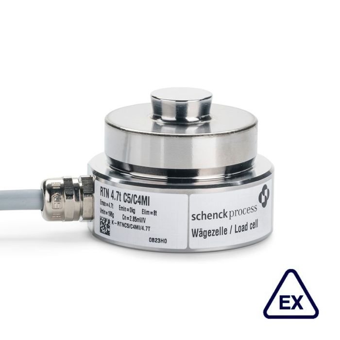
EX approvals
| Intrinsically safe explosion-proof design | Not intrinsically safe explosion-proof design | |||||
| ATEX / IECEx | II 2G Ex ia IIC T4 Gb (Zone 1) II 2D Ex ia IIIC T125°C Db, IP67 (Zone 21) |
II 3G Ex ec IIC T4 Gc (Zone 2) II 2D Ex tb IIIC T125 °C Db, IP67 (Zone 21) |
||||
| FM approval Canada | I / 0 / Ex ia / IIC / T4; -30°C < Ta < 40°C / Ga; 20 / Ex ia / IIIC / T125°C; -30°C < Ta < 40°C / Da; IP67. |
not available | ||||
| FM approval USA | IS / I, II, III / 1 / A, B, C, D, E, F, G / T4; -30°C < Ta < 40°C, I / 0 / AEx ia / IIC / T4; -30°C < Ta < 40°C / Ga; 20 / AEx ia / IIIC / T125°C; -30°C < Ta < 40°C / Da; IP67. |
not available | ||||
| EAC | 1Ex ia IIC T4 Gb (Zone 1) Ex ia IIIC T125°C Db X (Zone 21) |
2Ex nA II T4 Gc (Zone 2) Ex tb IIIC T125 °C Db X (Zone 21) |
||||
| KOSHA (only RTN 1 t – 4.7 t) |
Ex ia IIC T4 Gb (Zone 1) Ex ia IIIC T125°C Db, IP67 (Zone 21) |
Ex ec IIC T4 Gc (Zone 2) Ex tb IIIC T125 °C Db, IP67 (Zone 21) |
||||
| Accuracy class | 0.05 2GD |
C3 2GD | C5 / C4 Mi 7.5 2GD | 0.05 2D, 3G |
C3 2D, 3G | C5 / C4 Mi 7.5 2D, 3G |
| Design | Dxxxxxx .82 | Dxxxxxx .81 | Dxxxxxx .83 | Dxxxxxx .86 | Dxxxxxx .85 | Dxxxxxx .87 |
| Design KOSHA | D726173.92 (RTN 1 t) D726174.92 (RTN 2.2 t) D726175.94 (RTN 4.7 t) |
not available | not available | D726173.96 (RTN 1 t) D726174.96 (RTN 2.2 t) D726175.96 (RTN 4.7 t) |
not available | not available |
Load cells marked as intrinsically safe (Ex “i”) are operated in an intrinsically safe manner regardless of the zone.
CAUTION! The verification of intrinsically safe circuit must be verified. New barriers are provided in particular for new systems. Verifications of intrinsic safety are available for all load cells and barriers.
Order example:
47 t, precision class C3, ATEX category 2D, 3G. Type RTN 47 t C3 2D, 3G
Order number D724782.85

Reviews
There are no reviews yet.