

설명
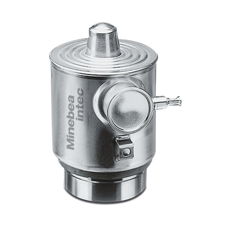
Load cell Pendeo® Process and mounting kits
Digital weighing technology for maximum transparency and precision
The digital compression load cells in the Pendeo® Process series are specially designed for silo and process vessel weighing. In combination with ‘DAT – Digital Assistance Technology’ from Minebea Intec, digital load cells provide new insights into the weighing process: from the load distribution in the container to temperature measuring.
Proven Minebea Intec technology for a wide range of applications
- Robust design ensures insensitivity to vibration and enables load capacities from 2 to 50 tonnes.
- Faster commissioning and shorter service times thanks to digital data processing
- High corrosion resistance due to high quality steel alloys ensures extremely long service life.
- Perfectly matched weighing electronics complete the digital measurement chain.
Technical specifications
PR 6204 – Load cell Pendeo® Process
| Parameter | Description | Abbr. | C3 | C6 | Unit |
| Accuracy class | 0.0125 | 0.008 | %Emax | ||
| Minimum dead load | Lowest limit of specified measuring range | Emin | 0 | %Emax | |
| Maximum capacity | Highest limit of specified measuring range | Emax | See Ordering information table | kg | |
| Safe load limit | Maximum load without irreversible damage | Elim | 150 | %Emax | |
| Destructive load | Danger of mechanical destruction | Ed | 300 | %Emax | |
| Minimum LC verification | Minimum load cell verification interval, vmin = Emax/Y For Emax = 2000 kg | Y Y | 14,000 10,000 | 20,000 / | |
| Deadload output return | Factor for deadload output return after load (DR = 1/2*Emax/Z) | Z | 3,000 | 8,000 | |
| Rated output | Relative output at maximum capacity | Cn | Standardised to Emax in (t) | ||
| Tolerance on rated output | Permissible deviation from rated output | dc | <0.07 | <0.07 | %Cn |
| Zero output signal | Load cell output signal under unloaded condition | Smin | <0.7 | <0.7 | %Cn |
| Reproducibility | Max. change in load cell output for repeated loading | R | <0.005 | <0.005 | %Cn |
| Creep | Max. change of output signal at Emax for 30 min. | dcr | <0.0125 | <0.008 | %Cn |
| Non-linearity1) | Max. deviation from best straight line through zero | dLin | <0.01 | <0.01 | %Cn |
| Hysteresis1) | Max. difference in LC output between loading and unloading | dhy | <0.0125 | <0.008 | %Cn |
| Temperature effect (TK) on Smin | Max. change of Smin in BT | TKSmin | <0.01 | <0.007 | %Cn/10 K |
| Temperature effect (TK) on parameter1) | Max. change of C in BT | TKC | <0.01 | <0.005 | %Cn/10 K |
| Insulation impedance | Between measuring circuit and housing at 50 VDC | RIS | > 1,000 × 106 | Ω | |
| Recommended supply voltage | To hold the specified performance | BU | 20 … 28 | VDC | |
| Nominal ambient temp. range | To hold the specified performance | BT | -10 … +40 | °C | |
| Usable ambient temp. range | Permissible for continuous operation without damage | BTU | -30 … +70 | °C | |
| Storage temperature range | Without electrical and mechanical stress | BTi | -40 … +95 | °C | |
| Permissible eccentricity | Permissible displacement from nominal load line | Sex | For 2 t …10 t: 10 For 25 t …50 t: 5 | mm | |
| Vibration resistance | Resistance against oscillations (IEC 60068-2-6 Fc) | 20 g, 100 h, 10 … 150 Hz | |||
| Barometric pressure influence | Influence of barometric pressure on output | PKSmin | 2 t: <200 5 t, 10 t: <320 From 25 t: 420 | g/kPa | |
| Nominal deflection | Max. elastic deformation under maximum capacity | Snom | Up to 25 t: <0.5 Up to 50 t: <0.8 | mm | |
| Material (housing) | Stainless steel 1.4301 | ||||
| Protection class | IP68 / IP69 | ||||
| Cable | Length: for Emax ≤10 t: 5 m, for Emax >10 t: 12 m Diameter: 5.8 mm Cross-section: 4 × 0.35 mm2 Cable sheath material: TPE | ||||
| Bending radius | ≥ 30 mm in case of fixed installation ≥ 70 mm in case of flexible installation | ||||
1) The data for non-linearity (dLin), hysteresis (dhy) and temperature effect on C (TKC) are typical values. For OIML R60 or NTEP approved load cells, the sum of these values is within the permissible cumulative error limits.
| Mounting kit PR 6001 | |||||||||||
| Maximum capacity of load cell PR 6204 | Mounting kit/ accessories | Material | Description/ comments | Mounting screws | Installation height (mm) | Max. permissible horizontal force (kN) | Max. permissible lift-off force (kN) | Max. permissible eccentricity | Max. permissible vertical load with- out load cell | Max. permissible load for jack-up | CE approval according to EN 1090 |
| 500 kg–10 t | PR 6001/00N | Steel electrogalva- nised, chromated and sealed (ROHS compliant) | Mounting kit including upper load disc | M12-8.8 | 190.5 | 10 | Yes | ||||
| PR 6001/00S | Stainless steel 1.4301 (AISI 304) | Mounting kit incl. upper and lower load disc | M12-A2-70 | / | |||||||
| Steel electrogalva- | |||||||||||
| PR 6001/10N | nised, chromated and sealed (ROHS compliant) | MaxiFLEXLOCK | M12-8.8 | 25 | 20 | ± 5 | 25 t | 1.5 t | Yes | ||
| PR 6001/10S | Stainless steel | MaxiFLEXLOCK | M12-A2-70 | / | |||||||
| 1.4301 (AISI 304) | |||||||||||
| Steel electrogalva- | |||||||||||
| PR 6001/20N | nised, chromated and sealed (ROHS compliant) | MaxiFLEXLOCK | M16-8.8 | 50 | Yes | ||||||
| PR 6001/20S | Stainless steel | MaxiFLEXLOCK | M16-A2-70 | / | |||||||
| 1.4301 (AISI 304) | |||||||||||
| PR 6001/30N | Steel electrogalva- nised, chromated and sealed (ROHS compliant) | High-load mount- ing kit incl. upper load disc | M20-8.8 | 250.5 | 200 | 180 | ± 5 | 25 t | 1.5 t | Yes | |
| 20 t–50 t | PR 6001/01N | Steel electrogalva- nised, chromated and sealed (ROHS compliant) | Mounting disc incl. upper load disc | M12-8.8 | 190.5 | 10 | Yes | ||||
| PR 6001/01S | Stainless steel 1.4301 (AISI 304) | Mounting kit incl. upper and lower load disc | M12-A2-70 | / | |||||||
| Steel electrogalva- | |||||||||||
| PR 6001/11N | nised, chromated and sealed (ROHS compliant) | MaxiFLEXLOCK | M12-8.8 | 25 | 30 | ± 5 | 25 t | / | Yes | ||
| PR 6001/11S | Stainless steel | MaxiFLEXLOCK | M12-A2-70 | / | |||||||
| 1.4301 (AISI 304) | |||||||||||
| Steel electrogalva- | |||||||||||
| PR 6001/21N | nised, chromated and sealed (ROHS compliant) | MaxiFLEXLOCK | M16-8.8 | 50 | Yes | ||||||
| PR 6001/21S | Stainless steel | MaxiFLEXLOCK | M16-A2-70 | / | |||||||
| 1.4301 (AISI 304) | |||||||||||
| Steel electrogalva- | |||||||||||
| PR 6001/26N | nised, chromated and sealed (ROHS | MaxiFLEXLOCK | M20-8.8 | 50 | Yes | ||||||
| compliant) | 250.5 | 180 | ± 5 | 25 t | / | ||||||
| PR 6001/31N | Steel electrogalva- nised, chromated and sealed (ROHS compliant) | High-load mount- ing kit incl. upper load disc | M20-8.8 | 200 | Yes | ||||||
| Mounting kit PR 6143 | ||||||||
| Maximum capacity of load cell PR 6204 | Mounting kit/ accessories | Material | Description/ comments | Mounting screws | Installation height (mm) | Max. permissible horizontal force (kN) | Max. permissi- ble lift-off force (kN)** | CE approval according to EN 1090 |
| 500 kg– 10 t | PR 6143/24S | Stainless steel 1.4542 | Base | / | / | / | / | / |
| 20 t–50 t | PR 6143/54S | Stainless steel 1.4542 | Base | / | / | / | / | / |
| 500 kg–50 t | PR 6143/50N | Steel electrogalvanised, chromated and sealed (ROHS compliant) | Upper load disc | / | / | / | / | / |
| PR 6143/50S | Stainless steel 1.4542 | Upper load disc | / | / | / | / | / | |
| PR 6143/00N | Steel electrogalvanised, chromated and sealed (ROHS compliant) | MiniFLEXLOCK incl. upper load disc | M12-8.8 | 190.5 | 25 | 32 | Yes | |
| PR 6143/00S | Stainless steel 1.4301 (AISI 304) | MiniFLEXLOCK incl. upper and lower load disc* | M12-A2-70 | / | ||||
| PR 6143/10N | Steel electrogalvanised, chromated and sealed (ROHS compliant) | MiniFLEXLOCK incl. upper load disc | M16-8.8 | 50 | 50 | Yes | ||
| PR 6143/10S | Stainless steel 1.4301 (AISI 304) | MiniFLEXLOCK incl. upper and lower load disc* | M16-A2-70 | / | ||||
* Lower load disc only for 0.5 t–10 t; for 20 t–50 t please order PR 6143/54S base separately ** With separate threaded rod
| Mounting kit PR 6144 | |||||||||
| Maximum capacity of load cell PR 6204 | Mounting kit/ accessories | Material | Description/ comments | Mounting screws | Installation height (mm) | Max. permissible horizontal force (kN) | Max. permissi- ble lift-off force (kN)** | Max. permissible out load cell | CE approval 1090 |
| 5 t– 50 t | PR 6144/54N | Steel electrogalvanised, chromated and sealed (ROHS compliant) | Seismic Mount incl. load cell dummy | M30-8.8 | 217 | 370 | 400 | 16 t | Yes |
vertical load with- according to EN ** With separate threaded rod
| Fixed bearing PR 6101 | ||||||
| Maximum capacity of load cell PR 6204 | Fixed bearing | Material | Mounting screws | Installation height (mm) | Max. usable load | Permissible hori- zontal force (kN) |
| 5 t | PR 6101/53N | Steel electrogalvanised, chromated and sealed (ROHS compliant) | M12-8.8 | 190.5 | 5 t | 15 |
| 10 t | 12 | |||||
| PR 6101/53S | Stainless steel 1.4301 (AISI 304) | M12-A2-70 | 5 t | 10 | ||
| 10 t | 8.5 | |||||
| 20 t | PR 6101/24N | Steel electrogalvanised, chromated and sealed (ROHS compliant) | M12-8.8 | 190.5 | 20 t | 45 |
| 40 t | 35 | |||||
| PR 6101/24S | Stainless steel 1.4301 (AISI 304) | M12-A2-70 | 20 t | 30 | ||
| 40 t | 20 | |||||
| 50 t | PR 6101/54N | Steel electrogalvanised, chromated and sealed (ROHS compliant) | M12-8.8 | 190.5 | 50 t | 100 |
| 75 t | 80 | |||||
| PR 6101/54S | Stainless steel 1.4301 (AISI 304) | M12-A2-70 | 50 t | 50 | ||
| 75 t | 20 | |||||
| Mounting kit PR 6145 | ||||||
| Maximum capacity of load cell PR 6204 | Mounting kit/ accessories | Material | Description/ comments | Mounting screws | Installation height (mm) | CE approval according to EN 1090 |
| 500 kg–50 t | PR 6145/00N | Steel electrogalvanised, chromated and sealed (ROHS compliant) | Plate mounting kit incl. upper load disc | M12-8.8 | 190.5 | Yes |
| PR 6145/00S | Stainless steel 1.4301 (AISI 304) | Plate mounting kit incl. upper and lower load disc* | M12-A2-70 | / | ||
* Lower load disc only for 0.5 t–10 t; for 20 t–50 t please order PR 6143/54S base separately
| PR 6024 cable junction box | ||
| Parameter | PR 6024/64S | PR 6024/68S |
| Number of load cells | 1 … 4 | 1 … 8 |
| Material | 1.4301, AISI 304 | 1.4301, AISI 304 |
| Protection class | IP66 / IP68 / IP69 | IP66 / IP68 / IP69 |
| ATEX approval | Zone 2/22 | Zone 2/22 |
| Usable ambient temp. range | -30 °C … +80 °C | -30 °C … +80 °C |
| Usable temperature range in EX area | -20 °C … +60 °C | -20 °C … +60 °C |
| Storage and transport | -30 °C … +80 °C | -30 °C … +80 °C |
| Supply voltage | 24 VDC | 24 VDC |
| PR 6024/62S power supply unit | |
| Material | 1.4301, AISI 304 |
| Protection class | IP66 / IP68 / IP69 |
| ATEX approval | Zone 2/22 |
| Usable temperature range | -30 °C … +80 °C |
| Usable temperature range in EX area | -20 °C … +50 °C |
| Storage and transport | -30 °C … +80 °C |
| Supply voltage | 100 … 240 VAC ±10%, 50/60 Hz |
| Power consumption | Max. 35 VA |
| Output voltage | 24 VDC |
| Supply and data cable PR 6124 | ||
| Parameter | PR 6124/xxD (Data cable) | PR 6124/xxP (Supply cable) |
|---|---|---|
| Cable type | Data cable | Supply cable |
| Cable diameter | 5.8 mm | 5.2 mm |
| Cable inductivity | A/C: 0.5 µH/kmA/A: 0.7 µH/km | — |
| Bending radii | Fixed installation: 30 mmRepeated bends: 70 mm | Fixed installation: 25 mmRepeated bends: 60 mm |
| Cable capacity | A/C: < 110 pF/mA/A: < 60 pF/m | — |
| Conduction resistance | ≤ 57 Ω/km | — |
| Operation temperature | -30 °C … +90 °C | -30 °C … +90 °C |
| Storage temperature | -40 °C … +90 °C | -40 °C … +90 °C |
| Short-term temperature | Briefly up to +125 °C | Briefly up to +125 °C |
| Test voltage | A/C: 800 VA/A: 1200 V | — |
| Oil resistance | VDE 0472 part 509, test type B | — |
| Flame resistance | VDE 0472 part 803EN 60332-1-2 | VDE 0472 part 803EN 60332-1-2 |
Technical diagrams
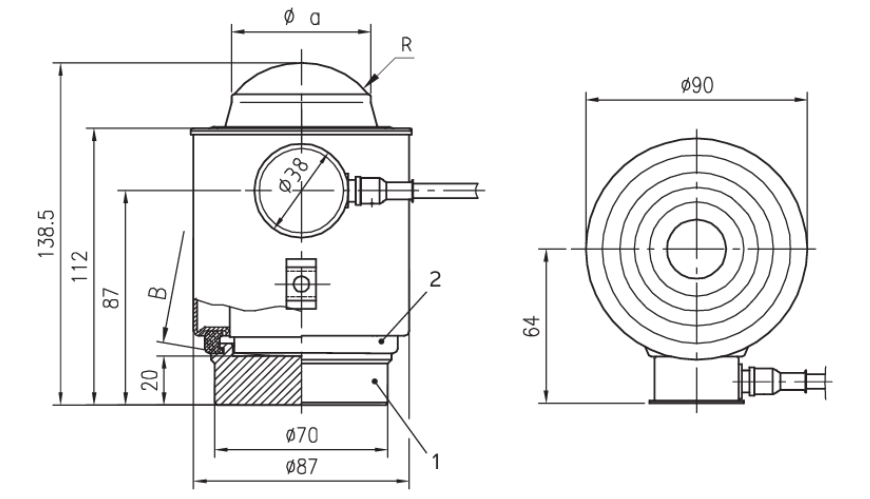
| Pos. | Designation |
| 1 | Lower load disc |
| 2 | Support ring |
| Model | B [mm] | Øa [mm] | R [mm] |
| PR 6204/2 t | 150 | 24 | 15 |
| PR 6204/5 t … 10 t | 150 | 34 | 15 |
| PR 6204/25t … 50t | 220 | 56 | 35 |
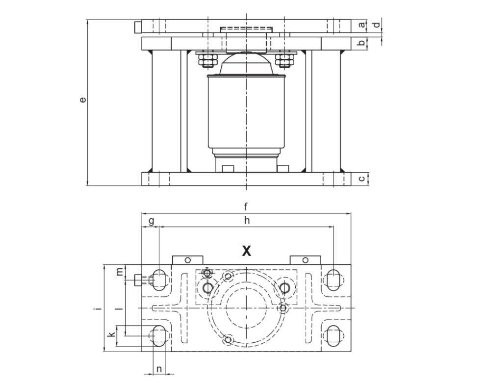
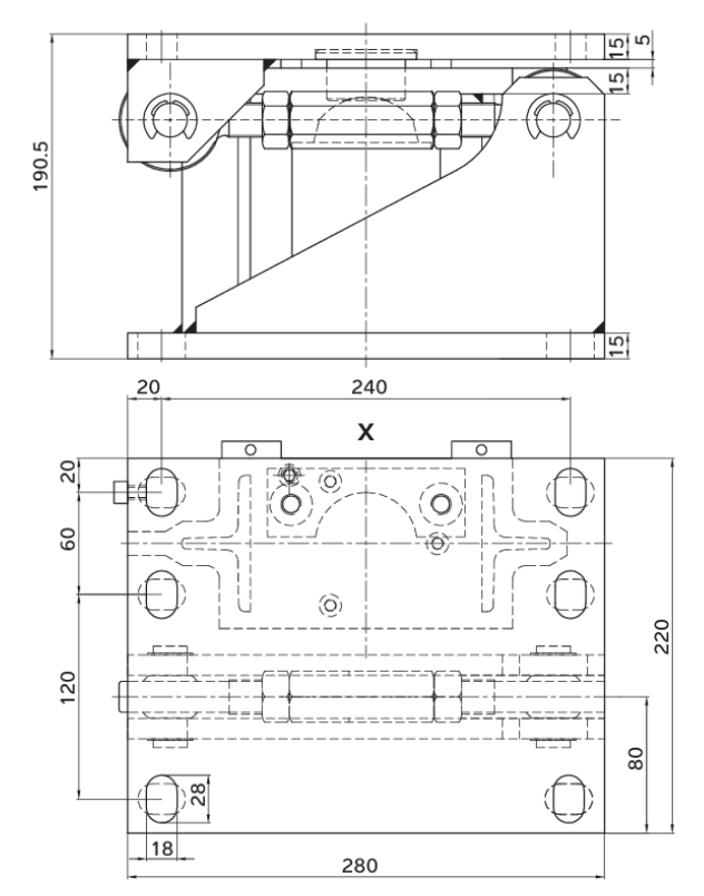
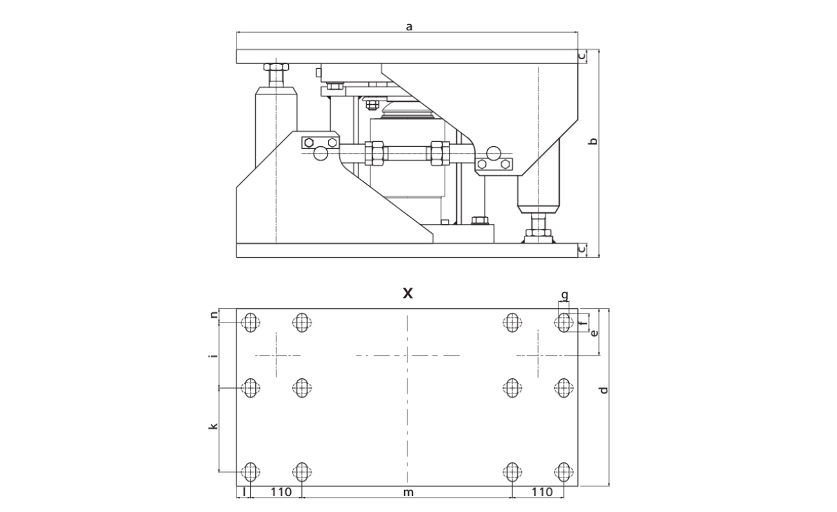
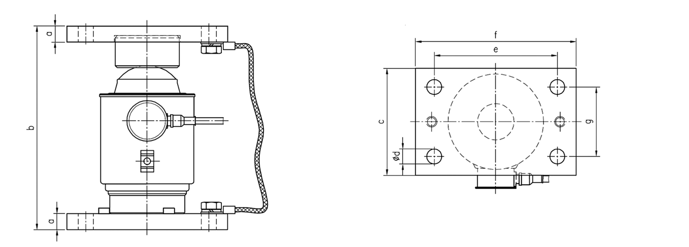
| Mounting kit | a | b | c | d | e | f | g | h | i | k | l | m | n |
| PR 6001/00 | 15 | 15 | 15 | 5 | 190.5 | 240 | 20 | 200 | 100 | 24 | 64 | 18 | 14 |
| PR 6001/01 | 15 | 15 | 15 | 5 | 190.5 | 240 | 20 | 200 | 100 | 24 | 64 | 18 | 14 |
 |
 |
|---|---|
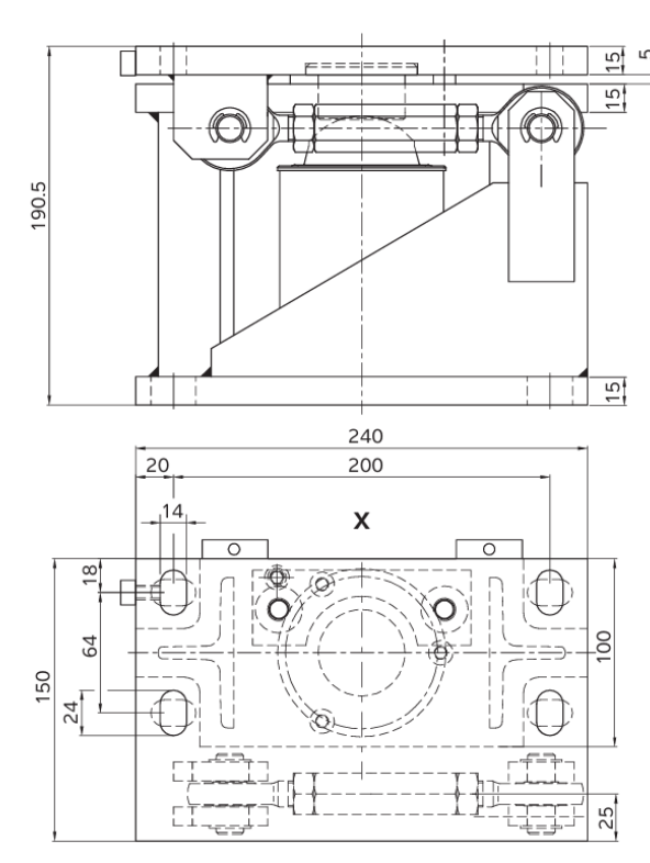
| Mounting kit PR 6001/10N+S | Mounting kit PR 6001/20N+S |
| Mounting kit | a | b | c | d | e | f | g | h | i | k | l | m |
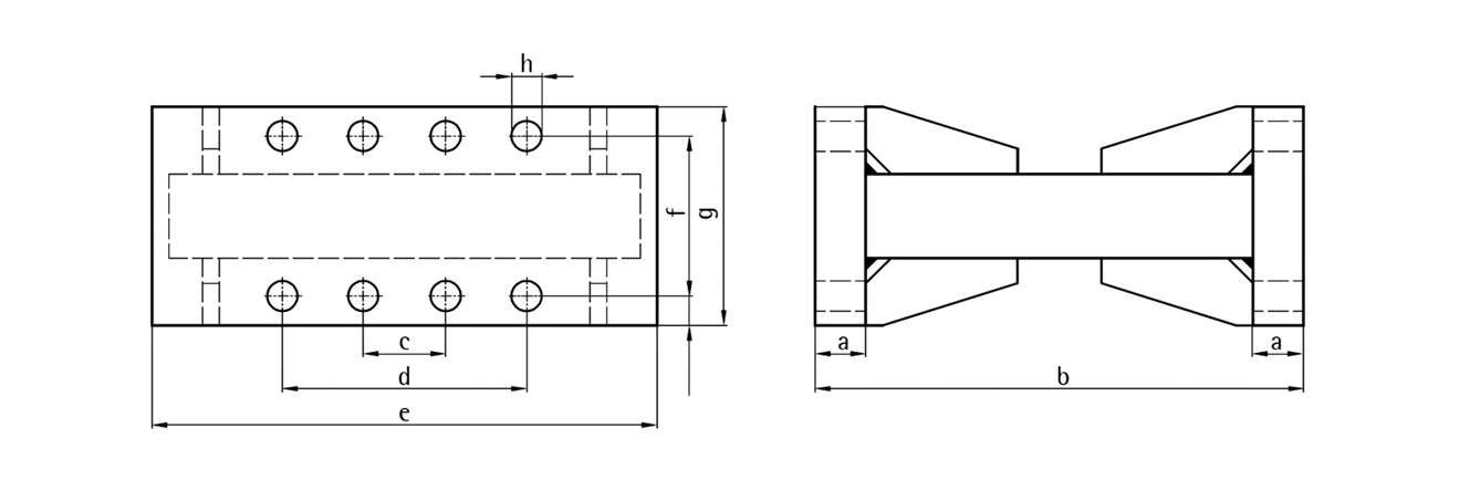
| PR 6001/30 | 600 | 250.5 | 30 | 320 | 60 | 40 | 22 | 30 | 70 | 190 | 30 | 320 |
| PR 6001/31 | 600 | 250.5 | 30 | 320 | 60 | 40 | 22 | 30 | 70 | 190 | 30 | 320 |
 |
 |
|---|---|
| Mounting kit PR 6001/11N+S | Mounting kit PR 6001/21N+S |

Mounting kit PR 6001/26N
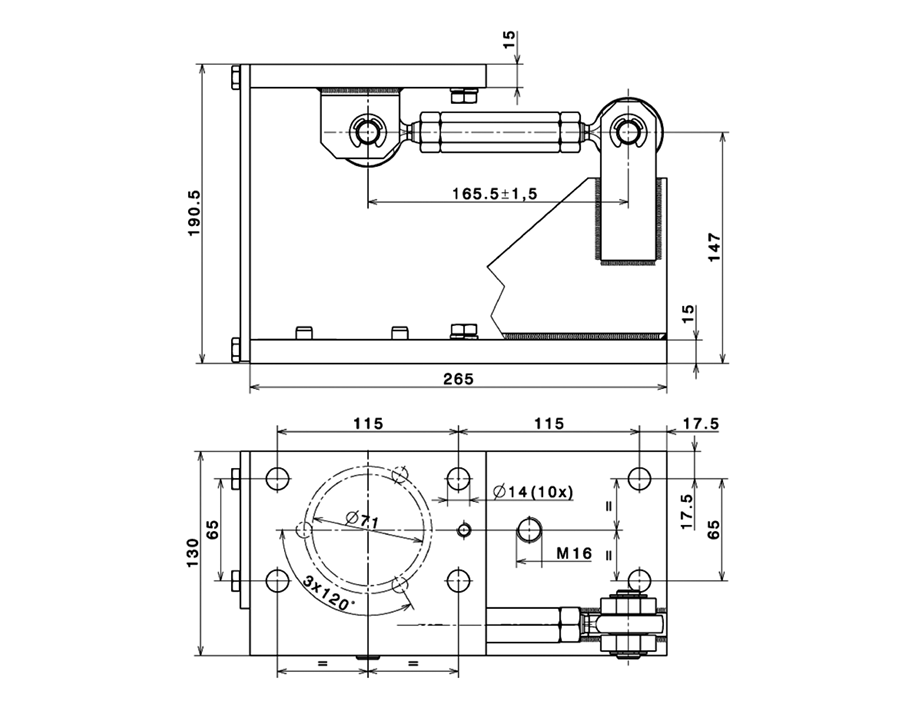
Mounting kit PR 6143/00N+S

Mounting kit PR 6143/10N+S
Mounting kit PR 6144
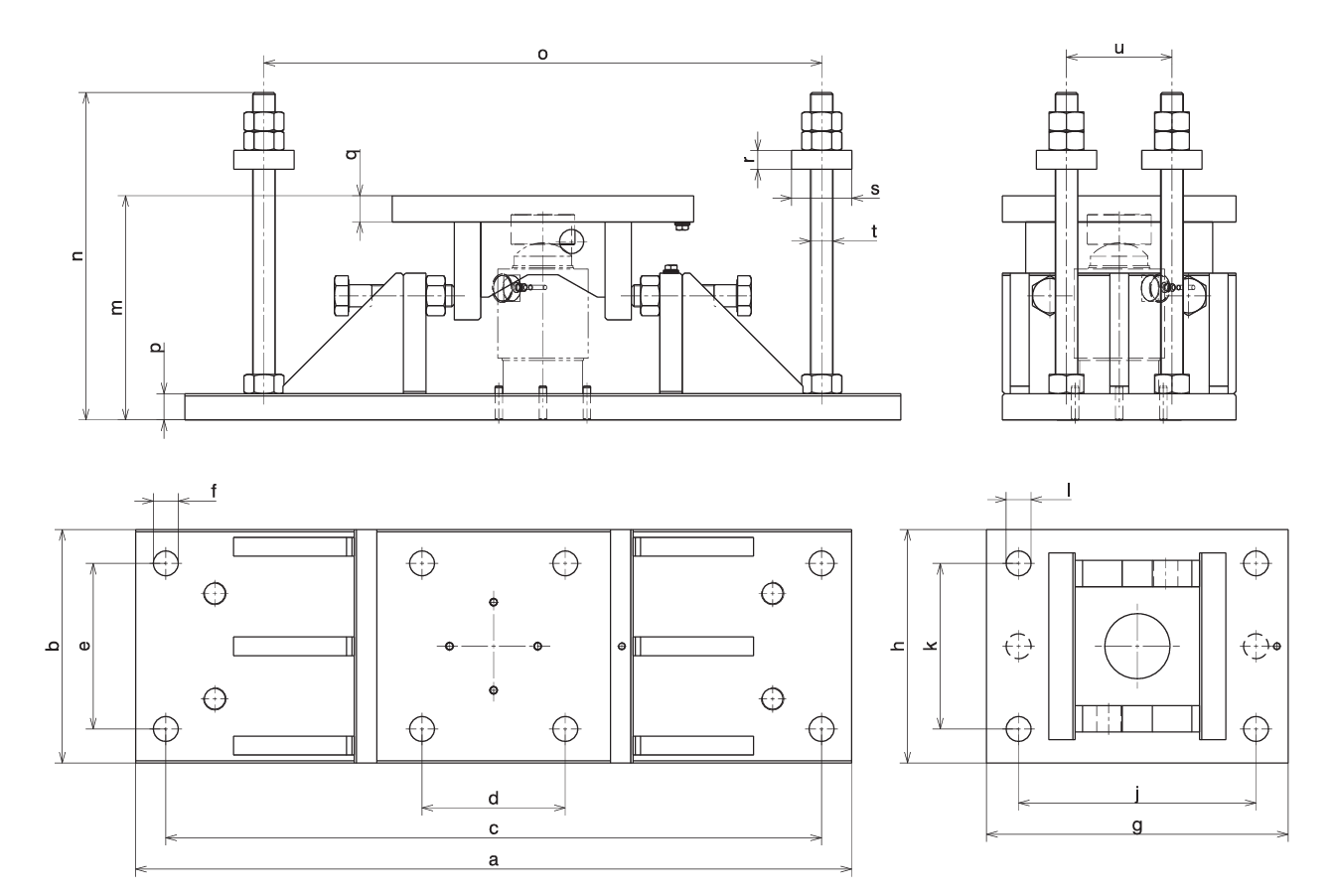
| Model | a | b | c | d | e | f | g | h | j | k | l | m | n | o | p | q | r | s | t | u |
| PR 6144/54 | 820 | 240 | 740 | 160 | 160 | Ø33 | 380 | 240 | 300 | 160 | Ø33 | 217 | 350 | 620 | 30 | 30 | 25 | Ø80 | M30 | 120 |
All dimensions in mm
Mounting kit PR 6145/xx
| Model | a | b | c | d | e | f | g |
| PR 6145/00 | 15 | 190.5 | 100 | 14 | 115 | 150 | 65 |
| Model | a | b | c | d | e | f | g | h |
| PR 6101/53 | 15 | 190.5 | – | 115 | 150 | 65 | 100 | 14 (4 ×) |
| PR 6101/24 | 15 | 190.5 | – | 115 | 150 | 65 | 100 | 14 (4 ×) |
| PR 6101/54 | 15 | 190.5 | 115 | 199 | 250 | 65 | 100 | 14 (8 ×) |
Fixed bearings PR 6101/53 / PR 6101/24 / PR 6101/54 / PR 6101/15 / PR 6101/25 / PR 6101/55
All dimensions in mm
| Cable junction box PR 6024 | ||
|
|
Cable junction box PR 6024/68S |
|
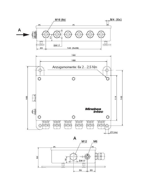 Cable junction box PR 6024/64S
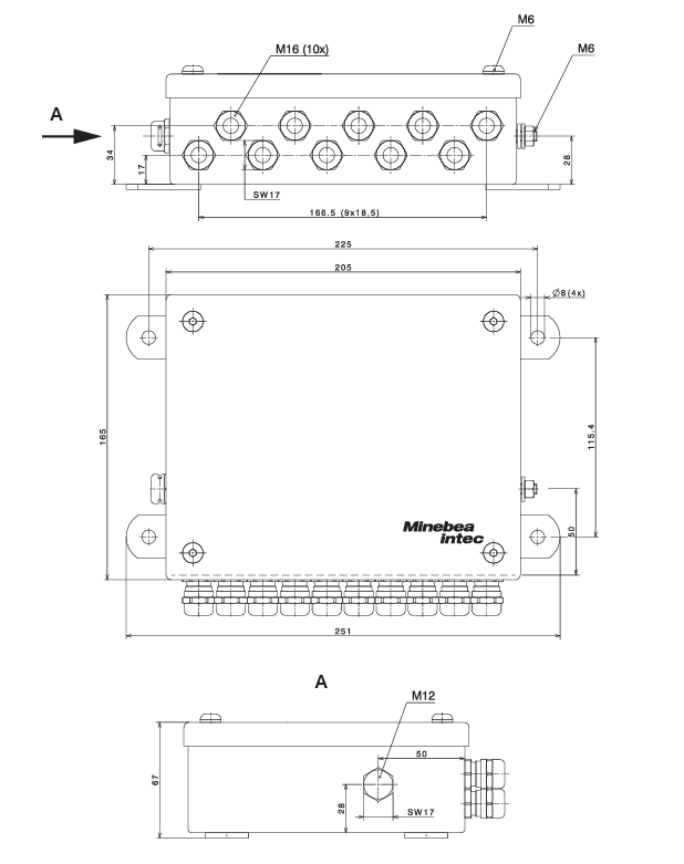
Power supply unit PR 6024/62S

Ex approval
Scope of validity: PR 6204 / PR 6024
| Certificates for digital compression load cell Pendeo® Process | |||
| Zone | Labelling | Certificate number | For |
| 2 | II 3G Ex nA IIC T5 Gc | Manufacturer’s declaration | All PR 6204/xx PR 6024/6x |
| 22 | II 3D Ex tc IIIC T90°C Dc | ||
Ordering information
| Digital vessel scale load cells OIML R60 accuracy class C3 = 0.015%, C6 = 0.008% | |
| Type | Order number |
| PR 6204/2tC3 | 940520423220 |
| PR 6204/5tC3 | 940520423250 |
| PR 6204/10tC3 | 940520423310 |
| PR 6204/25tC3 | 940520423325 |
| PR 6204/50tC3 | 940520423350 |
| PR 6204/25tC6 | 940520426325 |
| PR 6204/50tC6 | 940520426350 |
| Cable junction boxes | |
| Type | Order number |
| PR 6024/68S | 940536024684 |
| Power supply unit | |
| Type | Order number |
| PR 6024/62S | 940536024624 |
| Data and electrical supply cables | |
| Type | Order number |
| PR 6124/01D (1 m) | 940536124013 |
| PR 6124/01P (1 m) | 940536124014 |
| PR 6124/12D (100 m) | 940536124123 |
| PR 6124/12P (100 m) | 940536124124 |
| PR 6124/15D (150 m) | 940536124153 |
| PR 6124/15P (150 m) | 940536124154 |
| PR 6124/22P (200 m) | 940536124224 |
| PR 6124/31D (30 m) | 940536124313 |
| PR 6124/31P (30 m) | 940536124314 |
| PR 6124/51D (50 m) | 940536124513 |
| PR 6214/51P (50 m) | 940536124514 |
상품평
아직 상품평이 없습니다.