

설명
LE Series – Load Measuring Pin
Product Description
MAGTROL offers a wide range of Load-Force-Weight Transducers with optional integrated electronics or Load Monitoring Units (LMU) with B.I.T.E. functions creating an ideal measurement system which continuously checks for overloads and short circuits. Idealy for use on Safety Applications according to ECE-R10, ISO 13849-1 : CAT4 & PLe (LE 600 Series); ISO 13849-1 : CAT2 & PLd (LE 400 Series).
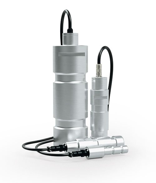
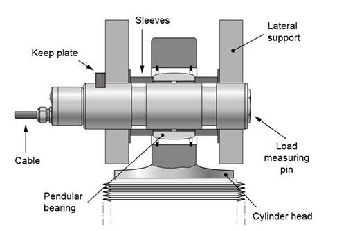
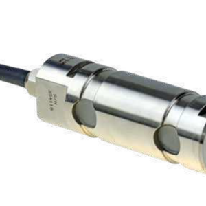
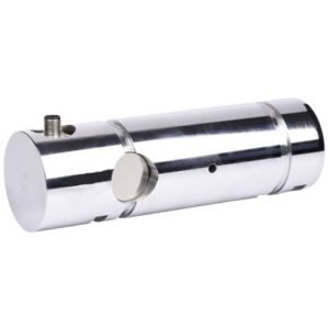
Magtrol Load Measuring Pins are used to measure load and force, and provide overload protection. The pins are mounted into machines in place of normal shafts and fitted with strain gauges, allowing them to produce a signal proportional to the measured load. Manufactured in Switzerland, Magtrol’s LE Series Load Measuring Pins are rugged with high resistance stainless steel and tight construction. Available in several standard ranges from 2.5 kN to 1 250 kN, their operation remains trouble-free and reliable even in electromagnetically difficult environmental conditions.
Design
Magtrol’s Load Measuring Pins have two circular grooves and an axial bore. Inside the central bore, adjacent to the external grooves, the strain gauges are mounted in a full-bridge configuration. The positioning and orientation of the strain gauges have been optimized by means of the finite element method (FEM).
Receive a quotation for a load pin according to your application’s dimensions by filling out our load pin inquiry form.
Features
- Temperature-compensated transducers with strain gauges in full-bridge configuration. On request, available with double bridge redundant.
- Available in several standard rangesfrom 2.5 kN…1 250 kN (0.28 tf…140.5 tf).
- Electronics for transmission over great distances:
· 2 wires (LE 200) 4…20 mA
· 3 wires (LE 400) 4…20 mA
· 6 wires (LE 600) available with dual channels 4…20 mA - Built-in test equipment (B.I.T.E.)included on LE 400 Series & LE 600 Series.
- Complies with Safety Standards ISO 13849-1 and IEC 62061.
- EMC execution for reliable trouble-free operation.
- Rugged design corresponding to the quality characteristics of LB 200 series.
- Insensitive to external mechanical and chemical effects.
- Ideal for use in hostile environments.
- Simple installation for cost-saving solutions to construction problems.
- Calibrated Output: 4…20 mA (LE).
Specifications-Drawings
For complete technical specifications and general dimension drawings, download the corresponding data sheet. For detailed dimension drawings. Click on the underlined link in the table below and a PDF document will open in a new window. Ratings apply to standard load pins only, special models are available by contacting Magtrol.
| Model(s) | Nominal Load (kN) |
Nominal Load (tf) |
Nominal Diameter (mm) |
LE 210 Series Downloads |
LE 410 Series (Axial Connector) Downloads |
LE 410 Series (Axial Cable) Downloads |
LE 610 Series (Axial Connector) Downloads |
LE 610 Series (Axial Cable) Downloads |
|---|---|---|---|---|---|---|---|---|
| LE 410 LE 610 |
2.5 | 0.28 | 25 | NA | LE 410 pdf | LE 410 with lubrication pdf |
LE 410 pdf | LE 410 with lubrication pdf |
LE 610 pdf | LE 610 with lubrication pdf |
LE 610 pdf | LE 610 with lubrication pdf |
| LE 211 LE 411 LE 611 |
5 | 0.56 | 25 | LE 211 pdf | step |
step | step | step | step |
| LE 212 LE 412 LE 612 |
10 | 1.12 | 25 | LE 212 pdf | step |
step | step | step | step |
| LE 213 LE 413 LE 613 |
20 | 2.25 | 25 | LE 213 pdf | step |
step | step | step | step |
| LE 214 LE 414 LE 614 |
50 | 5.62 | 35 | LE 214 pdf | step |
step | step | step | step |
| LE 216 LE 416 LE 616 |
100 | 11.24 | 50 | LE 216 pdf | LE 216 with lubrication pdf | step |
step | step | step | step |
| LE 217 LE 417 LE 617 |
200 | 22.48 | 65 | LE 217 pdf | LE 217 with lubrication pdf | step |
step | step | step | step |
| LE 218 LE 418 LE 618 |
500 | 56.20 | 85 | LE 218 pdf | LE 218 with lubrication pdf | step |
step | step | step | step |
| LE 220 LE 420 LE 620 |
1000 | 112.40 | 120 | LE 220 pdf | LE 220 with lubrication pdf | step |
step | step | step | step |
| LE 221 LE 421 LE 621 |
1250 | 140.50 | 120 | LE 221 pdf | LE 221 with lubrication pdf | step |
step | step | step | step |
LE 400 SERIES SPECIFICATIONS
| STANDARD VERSION 1 CHANNEL a) |
LE 410 | LE 411 | LE 412 | LE 413 | LE 414 | LE 416 | LE 417 | LE 418 | LE 420 | LE 421 |
|---|---|---|---|---|---|---|---|---|---|---|
| LOAD MEASURING | ||||||||||
| Nominal Load (Metric)b) | 2.5 kN | 5 kN | 10 kN | 20 kN | 50 kN | 100 kN | 200 kN | 500 kN | 1 000 kN | 1 250 kN |
| Nominal Load (US) b) | 0.28 tf | 0.56 tf | 1.12 tf | 2.25 tf | 5.62 tf | 11.24 tf | 22.48 tf | 56.2 tf | 112.4 tf | 140.5 tf |
| Overload Admissible (% of NL) | 150 % (of rated load without influence on measurement) | |||||||||
| Overload at Rupture (% of NL) | > 500 % | 400 % | 300 % | |||||||
| Non-linearity Error b) | < 0.25 % | < 0.5 % | ||||||||
| Non-linearity + Hysteresis Error b) | < 0.5 % | < 0.8 % | ||||||||
| Repeatability b) | ± 0.1 % | |||||||||
| Standard Calibration | 4 mA…20 mA corresponds to 0 kN – Full Scale Defection in kN | |||||||||
| MECHANICAL CHARACHTERISTICS & ENVIRONMENT | ||||||||||
| Technology | Full-bridge strain gauge | |||||||||
| Material | Stainless steel 1.4057 | |||||||||
| Lubrication | Not available | Oiler ø4 DIN 3405 D or M10 DIN 3405 A | ||||||||
| Operating Temperature | – 25 °C … + 80 °C | |||||||||
| Storage Temperature | – 30 °C … + 90 °C | |||||||||
| Temperature Influence on Zero b) | ± 0.02 % / K | |||||||||
| Temperature Influence on Sensitivity | ± 0.02 % / K | |||||||||
| Long Term Stability of Zero b) | < 1 % / year (not cumulative) | |||||||||
| Long Term Stability of Sensitivity | < 0.5 % / year (not cumulative) | |||||||||
| EMC | Vehicle approval | According to EN 61326-1, EN 61326-2-3 | ECE-R10 | |||||||||
| Angle influence on signal output c) | According to the cosine function | |||||||||
| Protection Class | IP 66 (connected) e) according to EN 60529 | |||||||||
| SAFETY STANDARDS & B.I.T.E. | ||||||||||
| Safety Standards | ISO 13849-1 : CAT2 and PLd | |||||||||
| Type of B.I.T.E. input | Active low, compatible with switch, relay, open collector or open drain, 1 B.I.T.E. input for each channel | |||||||||
| Effect on the output | Addition of 70 % (± 10 %) of the nominal load in standard (other % in option) | |||||||||
| ELECTRICAL CHARACTERISTICS & CONNECTIONS | ||||||||||
| Strain Gauge Bridge Impedance | 350 Ω | |||||||||
| Power Supply | 19 … 32 VDC (with protected polarity reversal) | |||||||||
| Output Signal | Rated 4 … 20 mA; max. 0.5 … 22 mA | |||||||||
| Configuration | 3-wires | |||||||||
| Output Connection | Integrated 3 m, 6 m, 12 m or 20 m, polymer cable K-424 (standard) d) or axial connector HUMMEL M16 |
|||||||||
a) Ratings apply to standard load pins only, special models available on request.
b) Full scale.
c) Variation of the measuring signal due to the angle positioning.
d) Other longer cable lengths available on request.
e) When the counter-connector is connected.
LE 600 SERIES SPECIFICATIONS
| STANDARD VERSION 2 CHANNELS a) |
LE 610 | LE 611 | LE 612 | LE 613 | LE 614 | LE 616 | LE 617 | LE 618 | LE 620 | LE 621 |
|---|---|---|---|---|---|---|---|---|---|---|
| LOAD MEASURING | ||||||||||
| Nominal Load (Metric)b) | 2.5 kN | 5 kN | 10 kN | 20 kN | 50 kN | 100 kN | 200 kN | 500 kN | 1 000 kN | 1 250 kN |
| Nominal Load (US) b) | 0.28 tf | 0.56 tf | 1.12 tf | 2.25 tf | 5.62 tf | 11.24 tf | 22.48 tf | 56.2 tf | 112.4 tf | 140.5 tf |
| Overload Admissible (% of NL) | 150 % (of rated load without influence on measurement) | |||||||||
| Overload at Rupture (% of NL) | > 500 % | 400 % | 300 % | |||||||
| Non-linearity Error b) | < 0.25 % | < 0.5 % | ||||||||
| Non-linearity + Hysteresis Error b) | < 0.5 % | < 0.8 % | ||||||||
| Repeatability b) | ± 0.1 % | |||||||||
| Standard Calibration | 4 mA … 20 mA corresponds to 0 kN – Full Scale Defection in kN | |||||||||
| MECHANICAL CHARACHTERISTICS & ENVIRONMENT | ||||||||||
| Technology | 2x Full-bridge strain gauge | |||||||||
| Material | Stainless steel 1.4057 | |||||||||
| Lubrication | Not available | Oiler ø4 DIN 3405 D or M10 DIN 3405 A | ||||||||
| Operating Temperature | – 25 °C … + 80 °C | |||||||||
| Storage Temperature | – 30 °C … + 90 °C | |||||||||
| Temperature Influence on Zero b) | ± 0.02 % / K | |||||||||
| Temperature Influence on Sensitivity | ± 0.02 % / K | |||||||||
| Long Term Stability of Zero b) | < 1 % / year (not cumulative) | |||||||||
| Long Term Stability of Sensitivity | < 0.5 % / year (not cumulative) | |||||||||
| EMC | Vehicle approval | According to EN 61326-1, EN 61326-2-3 | ECE-R10 | |||||||||
| Angle influence on signal output c) | According to the cosine function | |||||||||
| Protection Class | IP 66 (connected) e) according to EN 60529 | |||||||||
| SAFETY STANDARDS & B.I.T.E. | ||||||||||
| Safety Standards | ISO 13849-1 : CAT4 and PLe | |||||||||
| Type of B.I.T.E. input | Active low, compatible with switch, relay, open collector or open drain, 1 B.I.T.E. input for each channel | |||||||||
| Effect on the output | Addition of 70 % (± 10 %) of the nominal load in standard (other % in option) | |||||||||
| ELECTRICAL CHARACTERISTICS & CONNECTIONS | ||||||||||
| Strain Gauge Bridge Impedance | 2 x 350 Ω | |||||||||
| Power Supply | 19 … 32 VDC (with protected polarity reversal (1x or 2x)) | |||||||||
| Output Signal 2 Channels | Rated 4 … 20 mA; max. 0.5 … 22 mA (2x) | |||||||||
| Configuration | 6-wires | |||||||||
| Output Connection | Integrated 3 m, 6 m, 12 m or 20 m polymer cable K-824 (standard) d) or axial connector HUMMEL M16 |
|||||||||
a) Ratings apply to standard load pins only, special models available on request.
b) Full scale.
c) Variation of the measuring signal due to the angle positioning.
d) Other longer cable lengths available on request.
e) When the counter-connector is connected.
LE 200 SERIES SPECIFICATIONS
| STANDARD VERSION a) | LE 211 | LE 212 | LE 213 | LE 214 | LE 216 | LE 217 | LE 218 | LE 220 | LE 221 |
|---|---|---|---|---|---|---|---|---|---|
| LOAD MEASURING | |||||||||
| Nominal Load (Metric)b) | 5 kN | 10 kN | 20 kN | 50 kN | 100 kN | 200 kN | 500 kN | 1 000 kN | 1 250 kN |
| Nominal Load (US) b) | 0.56 tf | 1.12 tf | 2.25 tf | 5.62 tf | 11.24 tf | 22.48 tf | 56.2 tf | 112.4 tf | 140.5 tf |
| Overload Admissible (% of NL) | 150 % (without influence on measurement) | ||||||||
| Overload at Rupture (% of NL) | > 500 % | 400 % | 300 % | ||||||
| Non-linearity Error b) | < 0.25 % | < 0.5 % | |||||||
| Non-linearity + Hysteresis Error b) | < 0.5 % | < 0.8 % | |||||||
| Repeatability b) | ± 0.1 % | ||||||||
| Standard Calibration | 4 mA … 20 mA corresponds to 0 kN – Full Scale Defection in kN | ||||||||
| MECHANICAL CHARACHTERISTICS & ENVIRONMENT | |||||||||
| Technology | Full-bridge strain gauge | ||||||||
| Material | Stainless steel 1.4057 | ||||||||
| Lubrication | Not available | Oiler ø4 DIN 3405 D or M10 DIN 3405 A | |||||||
| Operating Temperature | – 25 °C … + 80 °C | ||||||||
| Storage Temperature | – 30 °C … + 90 °C | ||||||||
| Temperature Influence on Zero b) | ± 0.02 % / K | ||||||||
| Temperature Influence on Sensitivity | ± 0.02 % / K | ||||||||
| Long Term Stability of Zero b) | < 1 % / year (not cumulative) | ||||||||
| Long Term Stability of Sensitivity | < 0.5 % / year (not cumulative) | ||||||||
| EMC | According to EN 61000-6-2 & EN 61326-1 | ||||||||
| Influence α on Measurement Signal c) | According to the cosine function | ||||||||
| Protection Class | IP 66 according to DIN 60529 | ||||||||
| ELECTRICAL CHARACTERISTICS & CONNECTIONS | |||||||||
| Strain Gauge Bridge Impedance | 5 000 Ω | ||||||||
| Power Supply | 12 … 32 VDC (with protected polarity reversal <35 mA) | ||||||||
| Output Signal | Rated 4 … 20 mA; max. 3.5 … 25 mA | ||||||||
| Configuration | 2-wires | ||||||||
| Output Connection | Axial connector, Souriau 851 02 E 10 6P50connector d) | ||||||||
a) Ratings apply to standard load pins only, special models available on request.
b) Full scale.
c) Variation of the measuring signal due to the angle positioning.
d) Axial connector: Souriau 851 06 JC 10 6S50, 90° connector: Souriau 851 08 EC 10 6S50.
e) Other longer cable lengths available on request.
Operating Principles
When force is applied to the Load Measuring Pin along its sensitive axis, the effect on the strain gauge bridge results in an output signal proportional to the applied force. The signal is then converted by the integrated electronics to a standard 4 to 20 mA output. Based on SMD (Surface Mounted Device) technology, the electronics are well-protected against conducted and radiated electromagnetic fields.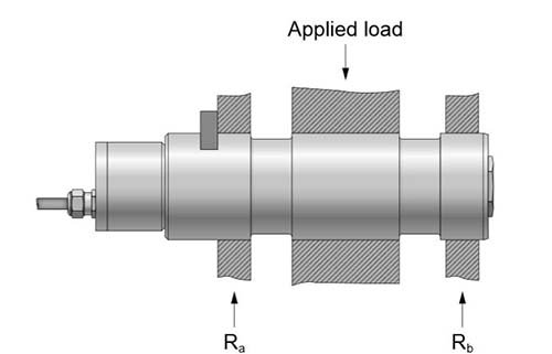
Applications
When forces acting on mechanical constructions are measured, the additional equipment required can often be costly and difficult to install. Magtrol Load Measuring Pins offer an excellent solution since they act as a direct element in the assembly, replacing a non-instrumented pin or shaft. LE Series Load Measuring Pins are used for measuring loads and overload protection on cranes, hoisting gear, elevators and winches. The integrated electronics makes them ideal for applications in which separate signal conditioning is difficult to install and where the monitoring electronics are positioned at extended distances.
상품평
아직 상품평이 없습니다.