

설명
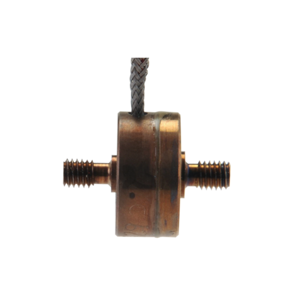
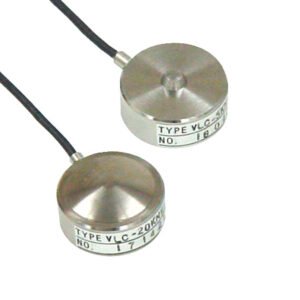
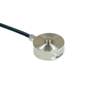
Model 11 Miniature Tension and Compression Force Sensor
Key features
- Subminiature design
- mV/V output
- Single diaphragm construction
About the Model 11 Miniature Tension and Compression Force Sensor
The Model 11 (tension/compression) subminiature loadcell is designed to measure load ranges up to 4kN. With subminiature dimensions, including diameters from .50 in to 0.75 in and height of 0.38 in, these units are easily incorporated into systems having limited space. The model achieves a non-linearity and hysteresis of 0.5 % full scale respectively and a frequency response of up to 58 kHz. A balance module is included in the load cell’s lead wire cable for zero balance, and should not be removed.
Technical Specifications
| Specification | Value |
|---|---|
| Hysteresis | ±0.5% of FS |
| Linearity | ±0.5% of FS |
| Load direction | Tension/compression |
| Non-repeatability | ±0.1% of FS |
| Operating temperature | -54°C to 121°C |
| Range | 1.5N – 5kN |
| Resolution | Infinite |
| Tolerance on output 1000g to 1000lb | 2mV/V (nominal) |
| Tolerance on output 1000g to 500g | 10mV/V (nominal) |
Performance specifications
| Characteristic | Measure |
| Load ranges7 | 150 g to 1000 lb |
| Linearity | ± 0.5 % full scale |
| Hysteresis | ± 0.5 % full scale |
| Non-repeatability | ± 0.1 % full scale |
| Tolerance on output 150 g to 500 g | 10mV/V(nominal) |
| Tolerance on output 1000 g to 1000 lb | 2mV/V(nominal) |
| Operation | Tension/compression3 |
| Resolution | Infinite |
| Maximum permissible torque 150 g to 100 lb | 4 in-lb |
| Maximum permissible torque 250 lb to 1000 lb | 20 in-lb |
Range codes
| Range codes | Range |
| AL | 150 g |
| AN | 250 g |
| AP | 500 g |
| AR | 1000 g |
| AT | 5 lb |
| AV | 10 lb |
| BL | 25 lb |
| BN | 50 lb |
| BR | 100 lb |
| CN | 250 lb |
| CR | 500 lb |
| CV | 1000 lb |
Environmental specifications
| Characteristic | Measure |
| Temperature, operating | -54 °Cto 121 °C[-65 °Fto 250 °F] |
| Temperature, compensated | 15 °Cto 71 °C[60 °Fto 160 °F] |
| Temperature effect, zero | 0.01 % full scale/°F |
| Temperature effect, span | 0.02 % reading/°F |
Wiring codes
| Cable | Unamplified |
| Red | (+) excitation |
| Black | (-) excitation |
| Green | (-) output |
| White | (+) output |
Electrical specifications
| Characteristic | Measure |
| Straingagetype 150 g to 500 g | Semiconductor |
| Straingagetype 1000 g to 1000 lb | Bonded foil |
| Excitation (calibration) | 5 Vdc |
| Insulation resistance | 5000 mOhm@ 50 Vdc |
| Bridge resistance (toler- ance) 150 g to 500 g | 500 ohm (nominal) |
| Bridge resistance (toler- ance) 1000 g to 1000 lb | 350 ohm (nominal) |
| Zero balance (tolerance) | ± 3 % of full scale (nominal) |
| Shuntcalibrationdata | Included |
| Electrical termination (std) | 1,83 m [5 ft] cable with balance board4 |
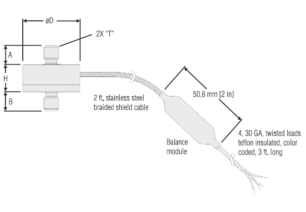
Mounting dimensions
| Ranges | ØD | T | H | A | B |
| 150, 250, 500, | 12,7 | #4-40 | 7,37 mm | 4,83 mm | 4,57 mm |
| 1000 g; 5, 10, | mm | UNC | [0.29 in] | [0.19 in] | [0.18 in] |
| 25, 50, 100 lb | [0.50 in] | ||||
| 250, 500, | 19,05 | 1/4-28 | 9,65 mm | 7,87 mm | 7,87 mm |
| 1000 lb | mm | UNF | [0.38 in] | [0.31 in] | [0.31 in] |
| [0.75] |
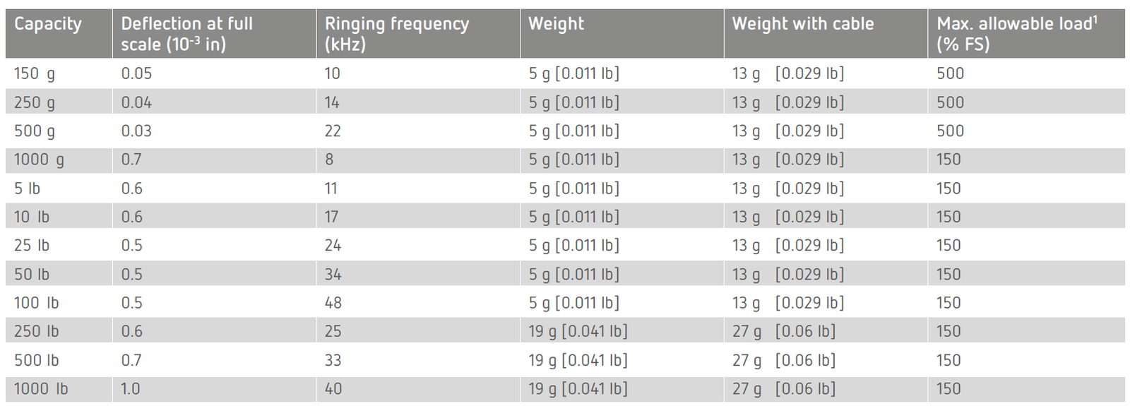
Deflections and ringing frequencies
Option codes
| Many range/option combinations are available in our quick-ship and fast-track manufacture programs. Please contact us. |
|
| Load range | 150 g, 250 g, 500 g, 1000 g, 5 lb, 10 lb, 25 lb, 50 lb, 100 lb, 250 lb, 500 lb, 1000 lb |
| Tempera- ture compen- sation | 1a. 60 °F to 160 °F 1b. 30 °F to 130 °F 1c. 0 °F to 185 °F 1e. -20 °F to 200 °F5 1f. 70 °F to 250 °F5 |
| Internal amplifiers | 2u. Unamplified, mV/Voutput |
| Electrical termina- tion | 5 ft integral cable with balance board4 6a. Bendix PTIH-10-6P – (or equivalent) 6 pin (max. 120 °C) onendofcable 6e. Integral cable: Teflon 6v. Phoenix connector on end of cable |
| Electrical termina- tion orien- tation | 15d. Connectoronendofcable |
| Special calibration | 30a. Compressiontestingonly, positiveincompression 30b. Tension and compression testing only, positive in tension 30c. Compressiontestingonly, negativeincompression |
| Shock and vibration | 44a. Shockandvibrationresistance |
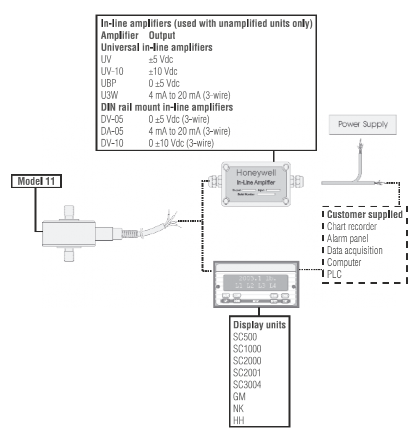
Typical system diagram

상품평
아직 상품평이 없습니다.