


설명
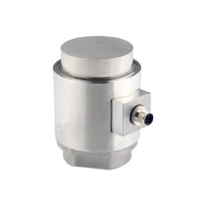
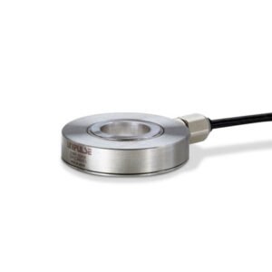
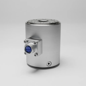
Honeywell / Model 41 Precision Low Profile Load Cell
FEATURES
• 0.1 % accuracy
• 5 lb to 500000 lb
• mV/V output (standard); 4 mA to 20 mA and 0 Vdc to 5 Vdc (optional) outputs
• Double diaphragm design
• Intrinsically safe available (2N option only)16
• CE approved17
PERFORMANCE SPECIFICATIONS
| Characteristic | Measure |
|---|---|
| Load ranges | 5 lb to 500000 lb |
| Non-linearity (5 lb to 25 lb) | ±0.2 % full scale |
| Non-linearity (50 lb to 500000 lb) | ±0.1 % full scale |
| Hysteresis (5 lb to 25 lb) | ±0.1 % full scale |
| Hysteresis (50 lb to 500000 lb) | ±0.08 % full scale |
| Non-repeatability (5 lb to 25 lb) | ±0.1 % full scale |
| Non-repeatability (50 lb to 500000 lb) | ±0.03 % full scale |
| Output (tolerance, 5 lb to 25 lb) | 2 mV/V ±0.5 % full scale |
| Output (tolerance, 50 lb to 500000 lb) | 3 mV/V ±0.5 % full scale |
| Operation | Compression/tension¹³ |
| Resolution | Infinite |
| Standard calibration | 5-point calibration: 0 %, 50 %, and 100 % of full scale in tension only |
ENVIRONMENTAL SPECIFICATIONS
| Characteristic | Measure |
|---|---|
| Temperature, operating | -54 °C to 121 °C [-65 °F to 250 °F] |
| Temperature, compensated | 15 °C to 71 °C [60 °F to 160 °F] |
| Temperature effect, zero | 0.002 % full scale/°F |
| Temperature effect, span | 0.002 % full scale/°F |
ELECTRICAL SPECIFICATIONS
| Characteristic | Measure |
|---|---|
| Strain gage type | Bonded foil |
| Excitation (calibration) | 10 Vdc |
| Insulation resistance | 5000 mOhm @ 50 Vdc |
| Bridge resistance (tolerance) | 350 ohm (nominal) |
| Zero balance (tolerance) | ±1 % full scale |
| Shunt calibration data | Included |
| Electrical termination (std), 5 lb to 5000 lb | PTIH-10-6P |
| Electrical termination (std), 7500 lb to 500000 lb | MS3102E-14S-6P |
| Mating connector, 5 lb to 5000 lb (not incl.) | PT06A-10-6S or equiv. (AA111) |
| Mating connector, 7500 to 500000 lb (not incl.) | MS3106A-14S-6S (AA121) |
MECHANICAL SPECIFICATIONS
| Characteristic | Measure |
|---|---|
| Maximum allowable load | 150 % FS¹ |
| Weight | See table |
| Material (less than 200,000 lb) | 17-4PH stainless steel |
| Material (greater than or equal to 300000 lb) | Carbon steel |
| Deflection | See table |
| Natural frequency | See table |
RANGE CODES
| Range Code | Available ranges | Range Code | Available ranges |
|---|---|---|---|
| AT | 5 lb | DV | 10000 lb |
| AV | 10 lb | EJ | 15000 lb |
| BL | 25 lb | EL | 20000 lb |
| BN | 50 lb | EN | 30000 lb |
| BR | 100 lb | EP | 50000 lb |
| CN | 250 lb | ER | 75000 lb |
| CR | 500 lb | ET | 100000 lb |
| CV | 1000 lb | FJ | 150000 lb |
| DL | 2000 lb | FL | 200000 lb |
| DN | 3000 lb | FN | 300000 lb |
| DP | 4000 lb | FP | 400000 lb |
| DR | 5000 lb | FR | 500000 lb |
| DT | 7500 lb | – | – |
WIRING CODES
| Pin | Function |
|---|---|
| A | (+) excitation |
| B | (+) excitation |
| C | (-) excitation |
| D | (-) excitation |
| E | (-) output |
| F | (+) output |
DEFLECTIONS AND RINGING FREQUENCIES
| Capacity (lb) | Deflection @ full scale (in) | Natural ringing frequency (Hz) | Weight (lb) |
|---|---|---|---|
| 5 to 25 | 0.001 | 2000 | 0.8 |
| 50 to 1000 | 0.002 | 4600 | 1.5 |
| 2000 to 5000 | 0.002 | 10000 | 2.0 |
| 7500 to 15000 | 0.003 | 6000 | 8.8 |
| 20000 to 50000 | 0.004 | 8000 | 11.0 |
| 75000 to 100000 | 0.006 | 5500 | 30.9 |
| 150000 to 200000 | 0.010 | 4500 | 46.3 |
| 300000 to 500000 | 0.010 | 4100 | 130.1 |
INTERNAL AMPLIFIERS
| Amplifier specifications |
Option 2b (Voltage) | Option 2c (Voltage) | Option 2t (Voltage) | Option 2j (Current 3-wire) | Option 2k (Current 2-wire) | Option 2n (Intrinsically Safe Amp) |
|---|---|---|---|---|---|---|
| Output signal | ±5 V / 0-5 V @ 45 mA | 0-10 V or ±10 V @ 45 mA | 4 mA to 20 mA | 4 mA to 20 mA | 4 mA to 20 mA | 4 mA to 20 mA |
| Input power (voltage) | ±15 Vdc or 26–32 Vdc | 11–28 Vdc | 15–28 Vdc | 22–32 Vdc | 9–32 Vdc | 9–28 Vdc |
| Input power (current) | 45 mA | 40 mA | 40 mA | 65 mA | 4–28 mA | 4–24 mA |
| Frequency response | 3000 Hz | 3000 Hz | 3000 Hz | 2500 Hz | 300 Hz | 2000 Hz |
| Power supply rejection | 60 dB | 60 dB | 60 dB | 60 dB | 60 dB | 60 dB |
| Operating temperature | -20 °F to 185 °F | -20 °F to 185 °F | -20 °F to 185 °F | 0 °F to 185 °F | 0 °F to 185 °F | -20 °F to 185 °F |
| Reverse voltage protection | Yes | Yes | Yes | Yes | Yes | Yes |
| Short circuit protection | Momentary | Momentary | Momentary | Yes | Yes | Yes |
| Wiring code: connector | A (+) Supply B Output common C Supply return D (+) Output E Shunt Cal 1 F Shunt Cal 2 | A (+) Supply B Output common** C Supply return** D (+) Output E Shunt Cal 1 F Shunt Cal 2 | A (+) Supply B Output common** C Supply return** D (+) Output E Shunt Cal 1 F Shunt Cal 2 | A (+) Supply B Output common** C Supply return** D (+) Output E Shunt Cal 1 F Shunt Cal 2 | A (+) Supply B No connection C No connection D (+) Output E Case ground F No connection | A (+) Supply B No connection C No connection D (+) Output E Case ground F No connection |
| Wiring code: cable | R (+) Supply Bl Output common G Supply return W (+) Output B Shunt Cal 1 Br Shunt Cal 2 | R (+) Supply Bl Output com* G Supply return* W (+) Output B Shunt Cal 1 Br Shunt Cal 2 | R (+) Supply Bl Output com* G Supply return* W (+) Output B Shunt Cal 1 Br Shunt Cal 2 | R (+) Supply Bl Output com* G Supply return* W (+) Output B Shunt Cal 1 Br Shunt Cal 2 | R (+) Supply Bl (+) Output W Case ground | R (+) Supply Bl (+) Output W Case ground |
* Black and green wires are internally connected.
** Pins B and C are internally connected.
*** See our Web site (http://measurementsensors.honeywell.com) for the most up-to-date information regarding intrinsically safe approvals, ref. #008-0547-00.
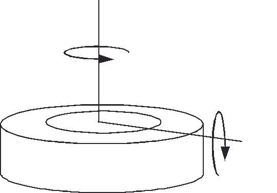
ALLOWABLE MAXIMUM LOADS
| Capacity (lb) | Side load (%) | Bending (%) | Torque (%) |
|---|---|---|---|
| 5 to 25 | 50 % | 40 % | 25 % |
| 50 to 1000 | 45 % | 35 % | 25 % |
| 2000 to 5000 | 30 % | 25 % | 25 % |
| 7500 to 30000 | 20 % | 20 % | 15 % |
| 50000 to 100000 | 20 % | 20 % | 15 % |
| 150000 to 200000 | 20 % | 20 % | 15 % |
| 300000 | 20 % | 20 % | 10 % |
| 400000 | 20 % | 20 % | 10 % |
| 500000 | 20 % | 20 % | 10 % |
OPTION CODES
| Category | Code | Description |
|---|---|---|
| Load ranges | – | 5, 10, 25, 50, 100, 250, 500, 1000, 2000, 5000, 3000, 4000, 7500, 10000, 15000, 20000, 30000, 50000, 75000, 100000, 150000, 200000, 300000, 400000, 500000 lb |
| Temperature compensation | 1a | 60 °F to 160 °F |
| 1b | 30 °F to 130 °F | |
| 1c | 0 °F to 185 °F | |
| 1d | -20 °F to 130 °F | |
| 1e | -20 °F to 200 °F | |
| 1f | 70 °F to 250 °F | |
| 1g | 70 °F to 325 °F | |
| 1h | 70 °F to 400 °F | |
| 1i | -65 °F to 250 °F | |
| 1j | 0 °C to 50 °C | |
| 1k | -20 °C to 85 °C | |
| 1m | -25 °C to 110 °C | |
| Internal amplifiers | 2b | 4-wire, ±5 Vdc |
| 2c | 0–5 Vdc output | |
| 2j | 4–20 mA (three-wire) output | |
| 2k | 4–20 mA (two-wire) output | |
| 2n (2N) | 4–20 mA intrinsically safe | |
| 2t | 0–10 Vdc output | |
| 2u | Unamplified, mV/V output | |
| Internal amplifier enhancements | 3a | Input/output isolation |
| 3d | Remote buffered shunt calibration | |
| Overload stops | 4a | Overload stops |
| Electrical termination | 6a | Bendix PTIH-10-6P 6-pin (≤5000 lb) |
| 6b | MS3102E-14S-6P (≥7500 lb) | |
| 6e | Integral cable: Teflon | |
| 6f | Integral cable: PVC | |
| 6g | Integral cable: Neoprene | |
| 6h | Integral cable: Silicone | |
| 6i | Integral underwater cable | |
| 6j | 1/2-14 conduit fitting with 5 ft 4-conductor PVC cable | |
| 6q | Molded integral cable polyurethane | |
| 6v | Phoenix connector on end of cable | |
| Shunt calibration | 8a | Precision internal resistor |
| Special calibration | 9a | 10-point (5 up/5 down) 20% increments @ 68 °F |
| 9b | 20-point (10 up/10 down) 10% increments @ 68 °F | |
| 9c | ASTM E-74 calibration | |
| Bridge resistance | 12b | 5000 ohm (foil) |
| Zero and span adjustment | 14a | No access to pots |
| 14b | Top access to pots | |
| Electrical connector orientation | 15a | Horizontal exit port orientation |
| 15b | Vertical exit port orientation | |
| 15c | Radial exit port orientation | |
| 15d | Connector on end of cable | |
| Special calibration (compression/tension) | 30a | Compression only calibration, positive in compression |
| 30b | Tension and compression calibration, positive in tension | |
| 30c | Compression only calibration, negative in compression | |
| 30d | Tension and compression calibration, positive in compression | |
| Bridge type | 31a | Dual bridge |
| Shock and vibration | 44a | Shock and vibration resistance |
| Interfaces | 53e | Signature calibration |
| 53t | TEDS IEEE 1451.4 module |
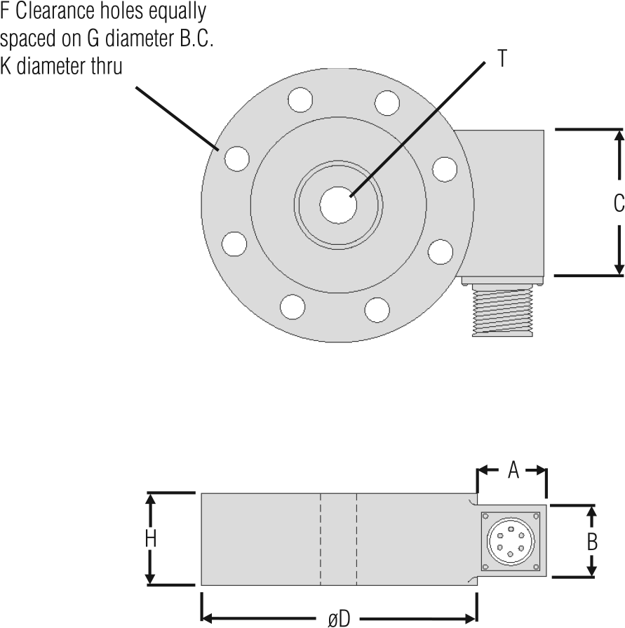
MOUNTING DIMENSIONS
| Ranges (lb) | D mm [in] | H mm [in] | H* mm [in]** | F# ØG mm [in] | B.C. ØK mm [in] | thru T | A mm [in] | A mm [in]* | B mm [in] | B mm [in]* | C mm [in] |
|---|---|---|---|---|---|---|---|---|---|---|---|
| 5, 10, 25 | 63,5 [2.50] | 20,32 [0.80] | 44,45 [1.75] | 6 50,8 [2.000] | 4,83 [0.19] | 1/4-28 UNF | 20,83 [0.82] | 63,5 [2.5] | 19,05 [0.75] | 22,86 [0.9] | 31,75 [1.25] |
| 50, 100, 250, 500, 1000 | 76,2 [3.00] | 25,4 [1.00] | 44,45 [1.75] | 6 57,15 [2.250] | 7,11 [0.28] | 3/8-24 UNF | 20,83 [0.82] | 63,5 [2.5] | 19,05 [0.75] | 22,86 [0.9] | 31,75 [1.25] |
| 2000, 3000, 4000, 5000 | 88,9 [3.50] | 25,4 [1.00] | 44,45 [1.75] | 6 66,68 [2.625] | 8,64 [0.34] | 1/2-20 UNF | 20,83 [0.82] | 63,5 [2.5] | 19,05 [0.75] | 22,86 [0.9] | 31,75 [1.25] |
| 7500, 10000, 15000 | 139,7 [5.50] | 45,7 [1.80] | 45,7 [1.80] | 8 114,3 [4.500] | 10,16 [0.40] | 1-14 UNS | 31,75 [1.25] | 58,42 [2.3] | 38,1 [1.50] | 38,1 [1.5] | 50,8 [2.00] |
| 20000, 30000, 50000 | 152,4 [6.00] | 45,7 [1.80] | 45,7 [1.80] | 8 123,83 [4.875] | 13,46 [0.53] | 1 1/2-12 UNF | 31,75 [1.25] | 58,42 [2.3] | 38,1 [1.50] | 38,1 [1.5] | 50,8 [2.00] |
| 75000, 100000 | 228,6 [9.00] | 63,5 [2.50] | 63,5 [2.50] | 12 196,85 [7.750] | 16,76 [0.66] | 2-12 UN | 31,75 [1.25] | 58,42 [2.3] | 38,1 [1.50] | 38,1 [1.5] | 50,8 [2.00] |
| 150000, 200000 | 279,4 [11.00] | 63,5 [2.50] | 63,5 [2.50] | 12 241,3 [9.500] | 19,81 [0.78] | 2 1/2-12 UN | 31,75 [1.25] | 58,42 [2.3] | 38,1 [1.50] | 38,1 [1.5] | 50,8 [2.00] |
| 300000, 400000, 500000 | 355,6 [14.00] | 107,95 [4.25] | 107,95 [4.25] | 12 298,45 [11.750] | 26,16 [1.03] | 3 1/2-8 UN | 31,75 [1.25] | 58,42 [2.3] | 38,1 [1.50] | 38,1 [1.5] | 50,8 [2.00] |
* Length of load cell with amplified option (see option codes)
** C dimension varies on high ranges. Consult factory
*** H dimension with 2n(2N) amplifier
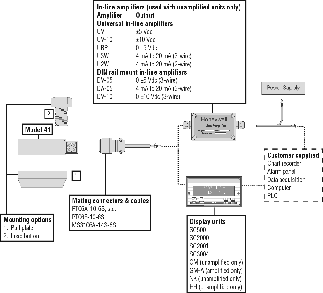
TYPICAL SYSTEM DIAGRAM
상품평
아직 상품평이 없습니다.