

설명
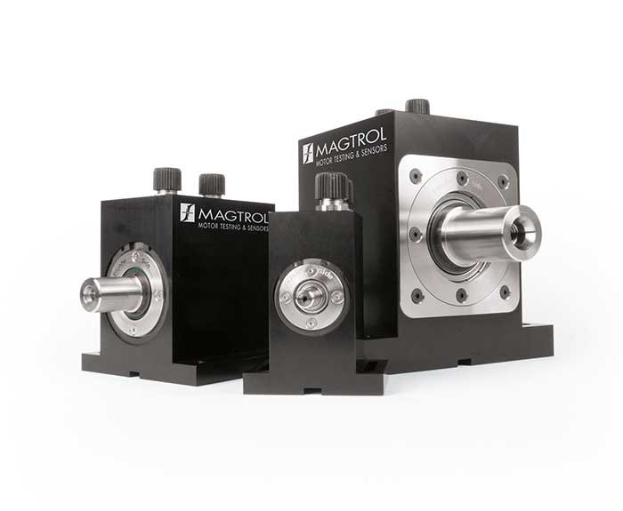
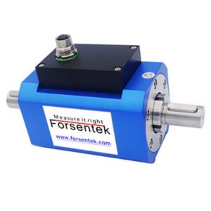
TS 100 Series – Torque Sensors
Product Description
Magtrol’s TS 100 Series In-LineTorque Sensors provide extremely accurate torque and speed measurement. Each model has an integrated conditioning electronic module providing 0 V DC to ± 5 V DC (±10 V DC) torque output through an 8-pole connector, as well as a USB interface which can be directly connected to a computer. The sensor is delivered with software allowing easy connection and data acquisition. A speed encoder provides a minimum of 360 PPR (Pulse Per Revolution) in Tach A, Tach B and Index reference Z (1 PPR). Magtrol Torque Sensors are very reliable, providing high overload protection, excellent long-term stability and high noise immunity. TS 100 Series sensor models are strain gauge-based measuring systems with imbedded telemetry signal transmission. Three LED lights located on the sensor cover allow a visual check of the sensor status by color code (combination of the 3 LEDs). The sensor is powered by 24 V DC (12 – 32 V DC) through its 8-pole connector. TARE & B.I.T.E. (Built-In Test Equipment) can be activated by either software or input from the 8-pole connector. Available torque ranges from 0.02 N·m … 500 N·m.
Features
- Integrated torque, speed and angle conditioning
- Torque range: from 0.02 N·m … 500 N·m
- Integrated speed encoder with index
- Accuracy: 0.05…0.075 %
- Overload capacity: 200 %
- Overload limit: 300 %
- Speed range: up to 15 000 rpm
- Torque output: ± 5 VDC (± 10 VDC)
- USB interface & analog connection
- LED operating status control
- Non-contact (no slip rings)
- Single DC power supply: 12 - 32 VDC
USB & Analog Output
The sensor offers both an isolated USB interface and an analog output. Both signals can be utilized simultaneously. For example, control loop data can be acquired using a computer via the USB interface while fast data acquisition can be performed using the analog output. In addition torque, speed, and angle data can be acquired using the USB interface while fast control loop data can be acquired using the analog output signals. The refresh time of the continuous analog signals is 100 μs (10 kHz). The analog signal provides a 0 to ± 5 VDC output corresponding to the sensor nominal range up to 200 % of measuring range (0 to ± 10 VDC). The USB interface can easily be connected and used with the LabVIEW™ dedicated software delivered with the sensor.
Integrated Encoder
TS 100 Series Torque Sensors integrate a high-end encoder with 360 PPR (Pulses Per Revolution) on 2 distinct signals (Tach A, Tach B) 90° out of phase providing an angular measurement resolution of ≤0.25°. A third signal offers 1 PPR (Z) providing an angular reference. The sensor body is marked with «Encoder Side» to indicate the encoder location. In low speed applications, where the angular position / accuracy of the test object is important, the encoder side needs to be directly connected to the test object so that the angular measurement is not influenced by the sensor deformation zone. Depending on sensor model, the number of pulses can be 360, 400 or 720 PPR (refer to specification table) and higher rate up to 5 000 PPR are available in option.
System Status Indicators
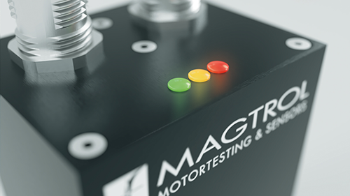 A color code is given by the activation of 3 LEDs lights (Yellow, Green, Red) located on the top cover of the sensor. This color code continuously communicates the operating status of the sensor, such as measuring status, tare functions, offset value, B.I.T.E. (Built-In Test Equipment) and overload.
Electrical Configuration

TS 100 Series Torque Sensor electrical input and output
Operating Principles
The measuring system is based on strain gauge technology directly applied on the sensor measuring section and connected in Wheatstone full bridge circuit. The strain gauge and its associated front end amplifier are powered by a high frequency power transfer. Under the applied torque, the measuring section will elastically deform providing a strain in the measuring elements. A microprocessor conditions the signal from the amplifier and transfers the measured values to the stator via contactless telemetry data transfer. On board micro-controllers manage all the internal functions, such as power transfer, data collecting and filtering, calibration and set-up, tare and B.I.T.E. (Build-In Test Equipment) functions, as well as the LED operating status control code. The sensor is supplied by 24 VDC (12 - 32 VDC) from the analog connector. The signal cutoff frequency can be digitally selected and configured in a range from 2 Hz up to 1 000 Hz.
Specifications and Drawings
| MODEL | NOMINAL RATED TORQUE (RT) (N·m) |
SHAFT DIAMETER (mm) |
ACCURACY CLASS (%) |
MAX SPEED (rpm) |
ENCODER RESOLUTION (ppr)a) |
TORSIONAL STIFFNESSc) (N·m/rad) |
MOMENT OF INERTIA (kg·m2) |
ANGULAR DEFORMATION (Degree) |
|---|---|---|---|---|---|---|---|---|
| TS 199 | 0.02 | 3 | 0.1 | 150 | 5 000 | 3.5 | 1.79 x 10⁻⁶ | 0.32 |
| TS 100 | 0.05 | 6 | 0.05 | 15 000 | 360b) | 24 | 1.96 x 10⁻⁶ | 0.15 |
| TS 101 | 0.1 | 6 | 0.05 | 15 000 | 360b) | 24 | 1.96 x 10⁻⁶ | 0.31 |
| TS 102 | 0.2 | 6 | 0.05 | 15 000 | 360b) | 58 | 1.97 x 10⁻⁶ | 0.23 |
| TS 103 | 0.5 | 6 | 0.05 | 15 000 | 360b) | 160 | 1.97 x 10⁻⁶ | 0.18 |
| TS 104 | 1 | 8 | 0.05 | 15 000 | 360b) | 330 | 2.19 x 10⁻⁶ | 0.17 |
| TS 105 | 2 | 8 | 0.05 | 15 000 | 360b) | 330 | 2.19 x 10⁻⁶ | 0.34 |
| TS 106 | 5 | 8 | 0.05 | 15 000 | 360b) | 665 | 2.23 x 10⁻⁶ | 0.42 |
| TS 107d) | 10 | 9 | 0.05 | 15 000 | 360b) | 1 020 | 2.34 x 10⁻⁶ | 0.46 |
| TS 108d) | 10 | 18 | 0.075 | 8 000 | 400b) | 1 800 | 3.14 x 10⁻⁵ | 0.32 |
| TS 109 | 20 | 18 | 0.075 | 8 000 | 400b) | 3 600 | 3.14 x 10⁻⁵ | 0.32 |
| TS 110 | 50 | 18 | 0.075 | 8 000 | 400b) | 7 400 | 3.38 x 10⁻⁵ | 0.39 |
| TS 111 | 100 | 19 | 0.075 | 8 000 | 400b) | 9 600 | 3.54 x 10⁻⁵ | 0.60 |
| TS 112 | 200 | 30 | 0.075 | 6 000 | 720 | 38 700 | 4.67 x 10⁻⁴ | 0.30 |
| TS 113 | 500 | 30 | 0.075 | 6 000 | 720 | 62 800 | 4.81 x 10⁻⁴ | 0.46 |
a) PPR means Pulse Per Revolution
b) Available with 1 000 PPR (speed limit 5 000 rpm) or 5 000 PPR (speed limit 1 000 rpm)
c) Calculated at the middle of shaft outputs
d) For 10 N·m, if speed does not exceed 8000 rpm, TS 108 is recommended
Torque Measurement
| Maximum Dynamic Torque Peak Value | 200 % of RT |
| Maximum Static Torque Without Damage | 300 % of RT |
| Resolution at RT | 11 000 points |
| Sampling Frequency | 16 bits at 10 000 sample / s |
| Combined Error of Linearity and Hysteresis | 0.05…0.1 % of RT f) |
| Noise Spectral Density | 2 ppm of RT / √ Hz typical e,f) |
| Speed Influence on Zero Torque | < 0.015 % / 1 000 rpm g) |
| Power Supply Change Sensitivity h) | < 50 (ppm of RT / V) |
e) Corresponds to < 0.05 % of RT, peak to peak over the entire 1 kHz bandwith.
f) Please refer to the “Accuracy Class” column in the table.
g) For TS 100 (0.05 N·m) and TS 101 (0.1 N·m) this parameter is degraded by a factor of 2.
h) Torque output change due to power supply change.
USB Speed & Angle Measurement
| MODEL | TS 100 – TS 107 | TS 109 – TS 111 | TS 112 – TS 113 |
|---|---|---|---|
| Speed & Angle Measurement | 360 PPR i,j), 2 signals 90° phase shift (quadrature X4) + Index Optical Encoder |
400 PPR i,j), 2 signals 90° phase shift (quadrature X4) + Index Optical Encoder |
720 PPR i,j), 2 signals 90° phase shift (quadrature X4) + Index Optical Encoder |
| Computed Speed Accuracy (USB Output) | < ± 0.05% k) | ||
| Angle Resolution (USB) | 0.25° | 0.225° | 0.125° |
| Accuracy | ± 0.25° over 360°. | ± 0.225° | ± 0.125° |
| Thermal drift | < 50 ppm over temperature range | ||
i) PPR means Pulse Per Revolution.
j) Available with 1 000 PPR (speed limit 5 000 rpm) or 5 000 PPR (speed limit 1 000 rpm).
k) Constant speed and based on the last 360° of rotation.
Environment & Certifications
| Storage Temperature | -40 °C to +85 °C |
| Operating Temperature | -25 °C to +80 °C |
| Temperature Influence on Zero / Sensitivity | < ± 0.1 % / 10 °C for the range -25 °C to +80 °C l) |
| Mechanical Shock | IEC 60068-2-27 : 2008 / Class C3 |
| Vibration Sinusoidal | IEC 60068-2-6 : 2007 / Class C3 |
| Protection Class | IP 44 (DIN EN 60529) |
| EMC / EMI Compatibility | IEC 61326-1 / IEC 61321-2-3 |
| Balancing Quality | G 2.5 according to ISO 1940 |
| Safety Standard | ISO 13849 / EN 62061 |
| Low voltage | IEC 61010-1 |
l) For TS 100 (0.05 N·m) this parameter is degraded by a factor of 2. Applicable to both analog and USB output.
System Configurations and Installation
The TS 100 Series Torque Sensor can be connected in various configurations. It can be used independently (via an external power supply) or in combination with other MAGTROL devices (e.g. DSP 7010 – Dynamometer Controller, Model 3411 – Torque Display,…). The sensors can be used with Magtrol software, such as M-TEST 7 or Torque 10 (included), to allow the data to be displayed and acquired. The double signal output, analog and USB can be used simultaneously. For example, one channel for data acquisition and the other one for closed loop control of a drive line.
USB Connection
When a TS 100 Series Torque Sensor is used solely with a USB connection, it must be supplied (12-32 VDC) through its analog connection.

TS 100 Series Torque Sensor USB only configuration
Analog with Dynamometer Controller
In this configuration example the power supply to the sensor is provided by the dynamometer controller. The DSP 7000 is a high speed programmable dynamometer controller. The analog only connection is used and data acquisition is supplied through a computer with M-TEST 7 software.
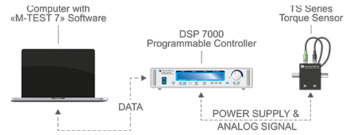
TS 100 Series Torque Sensor analog configuration connected to and power supplied by the DSP 7000
Analog & USB with Torque Display
In this configuration the power supply to the Sensor is provided by the torque display. The Model 3411 device is a torque / speed / power display. The TS 100 Torque Sensor’s USB connection to the computer supplies data acquisition using Torque 10 Software.

TS 100 Series Sensor configuration with Model 3411 Torque Display
Supported & Suspended Installations
The device can be used in both supported and suspended configurations. Supported configuration is recommended for the majority of applications (mandatory for high speed testing).
The TS 100 Series can be installed without the base mount in a suspended configuration. The benefit of this configuration is the use of a single element coupling creating a shorter drive train. This configuration is only applicable for low speed measurement.
CAUTION: TS 199-103 cannot be used in suspended installation as the weight of the sensor will degrade the accuracy of the measurement due to radial forces.

Suspended installation for low speed applications only. A single element coupling can be used to create a shorter drive train. This specific configuration cannot be used for TS 199-103.
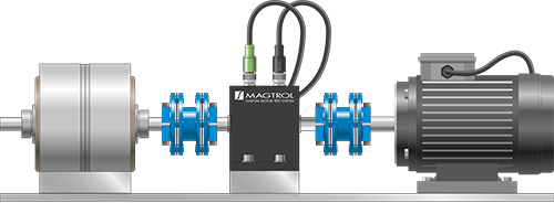
Supported installation Mandatory for standard and high speed applications.
Applications
TS 100 Series Torque Sensors provide dynamic torque and speed measurement of:
- Windshield wipers, electric windows, starters, generators and brakes in the automotive industry
- Pumps – water and oil
- Reduction gears and gearboxes
- Clutches
- Motorized valves & actuators
- Drills, pneumatic tools and other machine tools
- Torque & friction measurement in medical devices and the watch industry
상품평
아직 상품평이 없습니다.