

설명
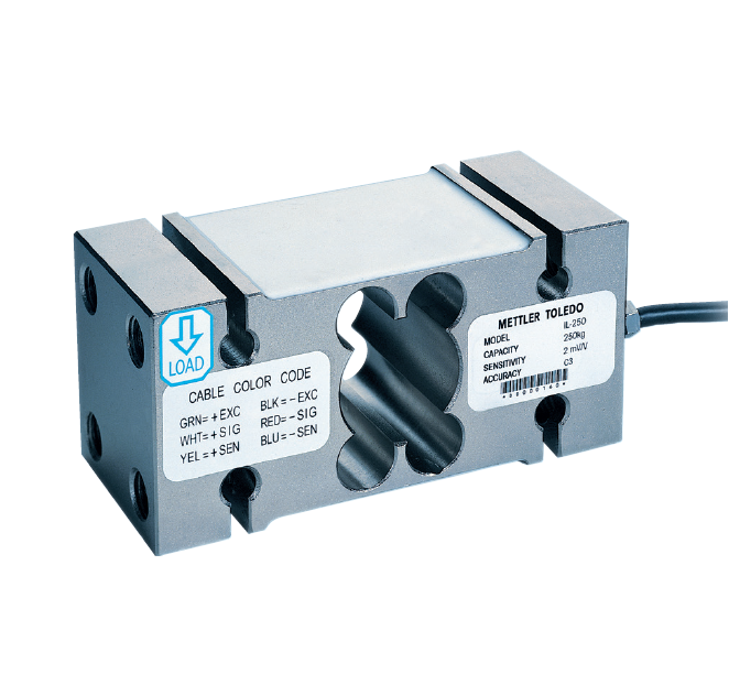
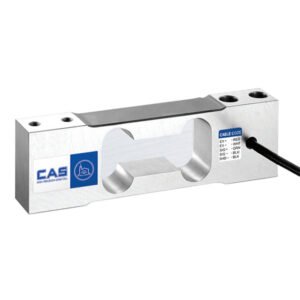
IL Single Point Load Cell
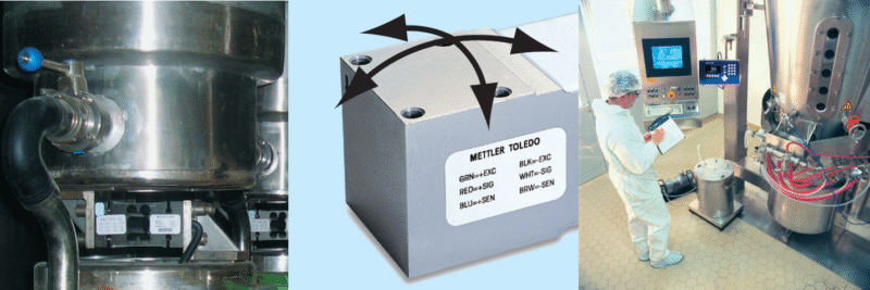
The IL is the ideal solution for hopper and bin weighing due to high capacities and large possible platform sizes. The mounting schema allows for direct bolting to a wall. The variety of capacities allows for wide application range.
| Parameter | Unit of measure | Specification | |||||
|---|---|---|---|---|---|---|---|
| Model No. | IL | ||||||
| Rated capacity (R.C.) | kg (lb, nominal) | 150 (331) | 250 (441) | 500 (1102) | 1000 (2204) | 2000 (4408) | |
| Rated output | mV/V @R.C. | 2 ± 0.002 | |||||
| Zero load output | %R.C. | ≤ 1 | |||||
| Combined error 1), 2) | %R.C. | ≤ 0.02 | |||||
| Repeatability error | %A.L. 3) | ≤ 0.01 | |||||
| Creep, 30 minute | %A.L. | ≤ 0.02 | |||||
| Min. dead load outputreturn (DR), 30 min | %A.L. | ≤ 0.016 | |||||
| Temperature effect on | Min. dead load output | %R.C./°C (../°F) | ≤ 0.002 (0.001) | ||||
| Sensitivity 2) | %A.L./°C (../°F) | ≤ 0.0009 (0.0005) | |||||
| Temperature range | Compensated | °C (°F) | -10 to +40 (+14 to +104) | ||||
| Operating | °C (°F) | -40 to +65 (-40 to +150) | |||||
| Safe storage | °C (°F) | -40 to +80 (-40 to +176) | |||||
| OIML / European approval 4) | OIML Cert. No. | R60/2000-NL-02.11 | |||||
| European Cert. No. | TC 6042 | ||||||
| Class | C3 | ||||||
| nmax | 3000 | ||||||
| Y | 5000 | ||||||
| PLC | 0.7 | ||||||
| Humidity symbol | None | ||||||
| Excitation voltage | Recommended | V AC/DC | 5 ~ 15 | ||||
| Max. | V AC/DC | 20 | |||||
| Terminal resistance | Excitation | Ω | 387±4 | ||||
| Output | Ω | 350±1 | |||||
| Insulation resistance @50VDC | MΩ | ≥ 5000 | |||||
| Breakdown voltage | V AC | > 500 | |||||
| Material | Spring element | Nickel plated alloy steel | |||||
| Enclosure | None | ||||||
| Cable entry fitting | 304 | ||||||
| Cable | PVC | ||||||
| Protection | Type | Potted | |||||
| IP rating | IP67 | ||||||
| Load limit | Safe | %R.C. | 150 | ||||
| Ultimate | %R.C. | 300 | |||||
| Safe dynamic load | %R.C. | 70 | |||||
| Fatigue life | cycles @R.C. | >1.000.000 | |||||
| Direction of loading | Compression | ||||||
| Weight, nominal | kg (lb) | 4.15 (9.2) | 5.4 (12) | ||||
| Cable | Length | m (ft) | 5 (16.6) | ||||
| Diameter | mm (in) | 5.8 (0.23) | |||||
| Barometric pressure effect on zero load output | kg/kPa (lb/in.Hg) | None | |||||
| Safe side load | %R.C. | 100 | |||||
| Overload protection | No | ||||||
| Mounting screw | Grade | 12.9 | |||||
| Size/thread | mm | M14 | M16 | ||||
| Engaged length | mm (in) | 25 1) | |||||
| Torque, nominal | N.m (ft-lb) | 98 (72) | 196 (143) | ||||
| Max. platter size | cm x cm (in x in) | 80×80 (3.15×3.15) | 100×100 (3.93×3.93) | ||||
| Off center load error @33%R.C. | %A.L./cm (../in) | 0.0045 (0.011) | 0.0035 (0.0087) | ||||
1) Error due to the combined effect of non-linearity and hysteresis
2) Typical values only. The sum of errors due to combined error and temperature effect on sensitivity comply with the requirements of OIML R60 and NIST HB44.
3) A.L. = Applied Load
4) See certificate for complete information
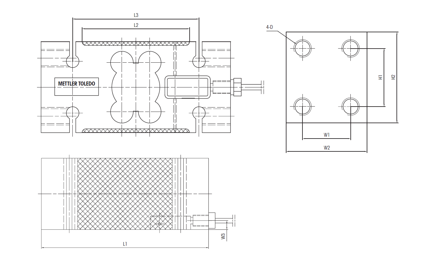
IL Load Cell Dimensional Drawings mm [inch]
| Capacity | Dimensions and locations | ||||||||
|---|---|---|---|---|---|---|---|---|---|
| D | H1 | H2 | L1 | L2 | L3 | W1 | W2 | W3 | |
| 150kg–1000kg[330–2204lb] | M14 | 46[1.81] | 72[2.83] | 15 0[5.91] | 85[3.35] | 100[3.94] | 38[1.50] | 64[2.52] | 8[0.31] |
| 2000kg[4409lb] | M16 | 55[2.17] | 80[3.15] | 150[5.91] | 85[3.35] | 100[3.94] | 42[1.65] | 72[2.83] | 8[0.31] |
IL Load Cell Order Information
| Description | Item No. |
|---|---|
| Load cell, model no. IL-150kg-5M | 71209638 |
| Load cell, model no. IL-250kg-5M | 71209639 |
| Load cell, model no. IL-500kg-5M | 71209635 |
| Load cell, modelno.IL-1000kg-5M | 71209640 |
| Load cell, modelno.IL-2000kg-5M | 71209780 |
IL Load Cell Cable Colours
| Colour | Function |
|---|---|
| Green | + Excitation |
| Black | – Excitation |
| White | + Signal |
| Red | – Signal |
| Yellow | + Sense |
| Blue | – Sense |
| Yellow (Long) | Shield |
상품평
아직 상품평이 없습니다.