

설명
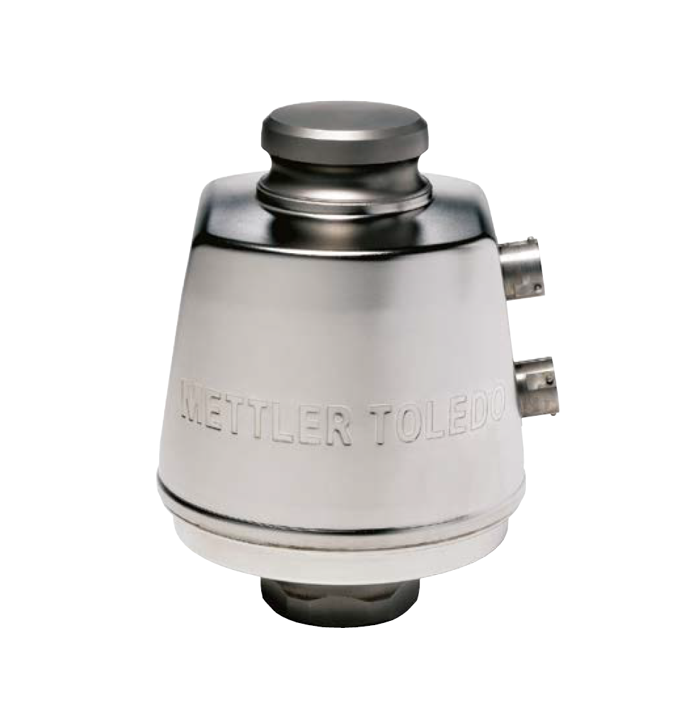
SLC820 POWERCELL® PDX® Load Cell
Vehicle Weighing
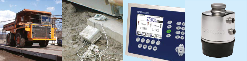
POWERCELL PDX load cells provide reliable weighing for heavy-capacity applications such as truck and rail scales. They are designed to perform in the toughest industrial environments and in the most forbidding cli-mates, from the tropics to the polar regions.
No Junction Boxes
POWERCELL PDX load cells connect to one another in a simple network that eliminates the need for high-maintenance junction boxes. Load cells, cables, and connectors are watertight, sealing the entire network against failures caused by floods and normal scale cleaning.
Advanced Diagnostics
Unlike other load cells, POWERCELL PDX load cells have a predictive diagnostics system that constantly monitors the perfor-mance of each load cell and automatically corrects for changes in temperature and other environmental factors. It instantly alerts the scale operator to any potential problems in the scale system.
Rocker Column
An integral rocker-column suspension automatically aligns the load cell for accurate weighing. A debris shield keeps the lower end of the rocker column free of debris and stones that can affect weighing accuracy.
| Parameter | Unit of Measure | Specification | ||||||||||
| Trade Name | POWERCELL PDX | |||||||||||
| Model Number | SLC820 | |||||||||||
| Load Cell Type | Column Compression, Digital Weight Processor (DWP) | |||||||||||
| Part Number | 42904882 | 42904883 | 42904884 | 42904885 | 42904891 | 42904892 | 30290638 | 72238150 | 72238147 | 30220694 | 30314022 | |
| Rated Capacity (R.C.)1 | t (klb, nominal) | 20 (44.1) | 30 (66.2) | 50 (110.3) | 90 (198.5) | 200 (440) | 300 (660) | |||||
| Sensitivity at R.C. | d @ R.C. | 200,000 | 300,000 | 500,000 | 900,000 | 200,000 | 300,000 | |||||
| Communication | Controller Area Network (CAN), Encrypted | |||||||||||
| Communication Rate | kbit/sec | 125 | ||||||||||
| Effective System Update Rate | Hz | 83 (with 4 cells), 50 (with 6 cells), 25 (with 14 cells), 15 (with 24 cells) | ||||||||||
| Effective System Synchronous Update Rate | Hz | 40 (with 10 cells) | ||||||||||
Weighing Performance
| Effect of Cable Length on System Accuracy | kg | 0 (Digital Signal) | |||||||||||
| Temperature Range | Compensated2 | °C (°F) | -10 to +40 (+14 to +104) | ||||||||||
| Operating3 | °C (°F) | -50 to +55 (-58 to +131) | |||||||||||
| Safe Storage | °C (°F) | -40 to +80 (-40 to +176) | |||||||||||
| Warm-up Time from Cold Start | minutes | 15 | |||||||||||
| Metrology | Class | C3/IIIL-M | C3/IIIL-M | C4/IIIL-M | C6 | C3/IIIL-M | C4/IIIL-M | C6 | C3/IIIL-M | C4/IIIL-M | C1 | C1 | |
| Linearity4 | ppm R.C. | < 100 | < 100 | < 100 | < 67 | < 100 | < 100 | < 67 | < 100 | < 100 | < 140 | < 140 | |
| Hysteresis4 | ppm R.C. | < 160 | < 160 | < 160 | < 110 | < 160 | < 160 | < 110 | < 160 | < 160 | < 220 | < 220 | |
| Temperature Effect on | Span4 | ppm R.C./°C | < ±13.3 | < ±13.3 | < ±10.0 | < ±6.6 | < ±13.3 | < ±10.0 | < ±6.6 | < ±13.3 | < ±10.0 | < ±26.7 | < ±26.7 |
| Combined Error4 | ppm R.C. | < 300 | < 300 | < 300 | < 200 | < 300 | < 300 | < 200 | < 300 | < 300 | < 800 | < 800 | |
| Creep at R.C. 10s to 30m | ppm R.C. | < ±150 | < ±150 | < ±125 | < ±83 | < ±150 | < ±125 | < ±83 | < ±150 | < ±125 | < ±500 | < ±500 | |
| Zero Return After 30 min at R.C. | ppm R.C. | < ±150 | < ±150 | < ±125 | < ±83 | < ±150 | < ±125 | < ±83 | < ±150 | < ±125 | < ±500 | < ±500 | |
| Barometric Pressure Effect on Zero Load Output | kg/kPa | < ±0.95 | < ±0.93 | < ±0.93 | < ±0.93 | < ±1.5 | < ±1.5 | < ±1.5 | < ±2.4 | < ±2.4 | < ±7.7 | < ±11.3 | |
| Zero Balance | %R.C. @ 20°C | < ±0.2 | |||||||||||
| Temperature Effect on Minimum Dead Load Output | kg/°C | < ±0.8*Vmin(OIML)/5°C | |||||||||||
| Humidity Effect, Continuous 100% RH | kg | 0 (Hermetic Seal) | |||||||||||
| Nonrepeatability | ppm R.C. | < ±50 | < ±200 | ||||||||||
Predictive Diagnostics (System)
| Breach Detection | % | Loss of Hermetic Seal |
| Maximum Overload | kg | Maximum Overload |
| Load Cell Temperature | °C | Minimum, Maximum, Current |
| Asset Management | Serial Number | |
| Load Cell Supply Voltage | V | Minimum, Current |
| Communication Signal Level | V | High, Low |
Metrological Approvals
| European/OIML Approval5 | Standard | OIML R60 | |||||||||||
| Number | T8426; TC7579; T2206; R60/2000-NL1-09:08 | ||||||||||||
| Class | C3 | C3 | C4 | C6 | C3 | C4 | C6 | C3 | C4 | C1 | C1 | ||
| nmax (OIML) | 3000 | 3000 | 4000 | 6000 | 3000 | 4000 | 6000 | 3000 | 4000 | 1000 | 1000 | ||
| Y | kg/kg | 8000 | 11,111 | 12,500 | 20,000 | 11,111 | 12,500 | 20,000 | 11,111 | 14,286 | 10,000 | 30,000 | |
| Vmin (OIML) | kg | 2.5 | 2.7 | 2.4 | 1.5 | 4.5 | 4.0 | 2.5 | 8.1 | 6.3 | 20 | 30 | |
| pLC | 0.8 | ||||||||||||
| Humidity Symbol | CH (Hermetic Seal) | ||||||||||||
| Min. Dead Load | kg | 50 | |||||||||||
| NTEP Approval5 | Standard | NIST Handbook 44 | |||||||||||
| Number | NTEP 08-090 | ||||||||||||
| Class | III L-M | ||||||||||||
| nmax (HB44) | 10,000 | 5000 | |||||||||||
| Vmin (HB44) | kg (lb, nominal) | 0.95 (2.1) | 1.0 (2.2) | 0.93 (2.0) | – | 1.7 (3.8) | 1.55 (3.4) | – | 3.2 (7.1) | 2.4 (5.3) | 7.7 (17) | 11.3 (25) | |
| Min. Dead Load | kg (lb, nominal) | 50 (110.3) | |||||||||||
1 R.C. = Rated or full capacity as specified on the data plate.
2 Certified according to approval agency or notified body (third party).
3 Operating temperatures below -40°C/-40°F require the load cell to be continuously powered.
4 The combined error of span, linearity error, and hysteresis will not exceed 80% of the error limits for OIML R60. OIML R60 C3 error limits are typically 60% tighter than the HB44 10K III L-M allowable tolerance.
5 See certificate for complete information.
| Parameter | Unit of Measure | Specification | ||||||||||
| Part Number | 42904882 | 42904883 | 42904884 | 42904885 | 42904891 | 42904892 | 30290638 | 72238150 | 72238147 | 30220694 | 30314022 | |
| Rated Capacity (R.C.) | t (klb, nominal) | 20 (44.1) | 30 (66.2) | 50 (110.3) | 90 (198.5) | 200 (440) | 300 (660) | |||||
Electrical
| Connectors | Quick-Connect with Bayonet Lock, 5 Pins, Stainless Steel, Glass-to-Metal Seal, Laser Welded | ||
| Cable | Exterior Braided Stainless Steel Armor, PVC Chemically Resistant Jacket, 9mm O.D., 5 Conductors, Triple Shielded and Dual Drain Wires | ||
| Cable Length, Cell to Cell (typical) | m (ft, nominal) | 2 to 14 (6.5 to 46) | |
| Cable Length, Home Run (typical) | m (ft, nominal) | 10 to 300 by 10 increments (33 to 984 by 33 increments) | |
| Supply Voltage by Terminal (Regulated in the Load Cell) | Typical | V DC | 12 or 24 |
| Minimum/Maximum | V DC | 7.5 / 28 | |
| Lightning Protection6 Max. Tested (SAE ARP5412) | A | > 80,000 | |
| Surge Protective Device | Integral | ||
| Insulation Resistance at 50VDC | MΩ | ≥ 2000 | |
| Breakdown Voltage | V AC | ≥ 500 | |
Mechanical
| Material | Spring Element | 17-4 PH Stainless Steel (magnetic) | 420 Stainless Steel | |||||
| Enclosure | Electropolished 304 Stainless Steel, 1mm Wall Thickness, Laser Welded | |||||||
| Low-Profile Receivers | 17-4 PH Forged and Machined Stainless Steel, Hardened | |||||||
| Anti-Rotation | Integral, 6-Point Hexagonal Mount | |||||||
| Protection | Type | Hermetic (submersible) | ||||||
| IP Rating | IP68 (1m – 7 days submersion), IP69K test reports on file | |||||||
| NEMA Rating | NEMA 6P (submersible) | |||||||
| Load Limit | Safe | %R.C. | 200 | 150 | ||||
| Ultimate | %R.C. | 300 | 200 | |||||
| Safe Dynamic Load | %R.C. | 70 | ||||||
| Fatigue Life at R.C. | Cycles | > 1,000,000 | ||||||
| Direction of Loading | Compression | |||||||
| Deflection at R.C., typical | mm (in) | 0.36 (0.014) | 0.51 (0.020) | 0.71 (0.028) | 1.02 (0.040) | – | ||
| Horizontal Restoring Force | %A.L./mm7 | 1.82 | 1.82 | 1.82 | 1.60 | 1.59 | ||
| Shipping Weight, nominal | kg (lb) | 3.0 (6.6) | 3.0 (6.6) | 3.2 (7.0) | 7.5 (16.6) | 12.8 (28.2) | 29 (63.9) | |
6 Tested with an IND780 terminal and lightning protection kit by Lightning Technologies, Inc. (80,000A).
7 Percent of the vertical applied load (A.L.) per mm of horizontal displacement.
| Parameter | Unit of Measure | Specification | ||||||||||
| Part Number | 42904882 | 42904883 | 42904884 | 42904885 | 42904891 | 42904892 | 30290638 | 72238150 | 72238147 | 30220694 | 30314022 | |
| Rated Capacity (R.C.) | t (klb, nominal) | 20 (44.1) | 30 (66.2) | 50 (110.3) | 90 (198.5) | 200 (440) | 300 (660) | |||||
Hazardous Area
| ATEX Zone 1/21 | Agency | FM Approvals Ltd. | |
| Certificate Number | FM17ATEX0023 | ||
| Standards | EN 60079-0:2012+A11:2013, EN 60079-11:2012, EN 60529:1991+A1:2000+A2:2013 | ||
| Gas Rating | II 2 G Ex ib IIB T4 Gb | ||
| Dust Rating | II 2 D Ex ib IIIC T130°C Db | ||
| IS Parameters | Power: Ui = 8.4V, Ii = 100mA, Pi = 0.84W, Ci = 27.5uF, Li = 17.7uH; CANbus: Ui = 8.4V, Ii = 100mA, Pi = 0.84W, Ci = 27.5uF, Li = 0uH | ||
| Temperature Range | -40°C ≤ Ta ≤ +55°C | ||
| Installation Instructions | 30343366 | ||
| IECEx Zone 1/21 | Agency | FM Approvals LLC | |
| Certificate Number | IECEx FMG 17.0010 | ||
| Standards | IEC 60079-0:2011 Edition 6.0, IEC 60079-11:2011 Edition 6.0 | ||
| Gas Rating | Ex ib IIB T4 Gb | ||
| Dust Rating | Ex ib IIIC T130°C Db | ||
| IS Parameters | Power: Ui = 8.4V, Ii = 100mA, Pi = 0.84W, Ci = 27.5uF, Li = 17.7uH; CANbus: Ui = 8.4V, Ii = 100mA, Pi = 0.84W, Ci = 27.5uF, Li = 0uH | ||
| Temperature Range | -40°C ≤ Ta ≤ +55°C | ||
| Installation Instructions | 30343366 | ||
| FM Division 1 Zone 1/21 | Agency | FM Approvals LLC | |
| Certificate Number | FM17US0025 | ||
| Standards | FM Class 3600:2011, FM Class 3610:2015, FM Class 3810:2005; ANSI/ISA 60079-0:2013, ANSI/ISA 60079-11:2014, ANSI/IEC 60529:2004 | ||
| Gas Rating | Class I, Division 1, Groups C, D, Temperature Class T4; Class 1, Zone 1, AEx ib IIB T4 Gb | ||
| Dust Rating | Class II, Division 1, Groups E, F, G, Temperature Class T4; Zone 21, AEx ib IIIC T130°C Db | ||
| Fiber Rating | Class III, Division 1 | ||
| IS Parameters | Power: Ui = 8.4V, Ii = 100mA, Pi = 0.84W, Ci = 27.5uF, Li = 17.7uH; CANbus: Ui = 8.4V, Ii = 100mA, Pi = 0.84W, Ci = 27.5uF, Li = 0uH | ||
| Temperature Range | -40°C ≤ Ta ≤ +55°C | ||
| Control Drawing | 30343367 | ||
| CSA Division 1 Zone 1/21 | Agency | FM Approvals LLC | |
| Certificate Number | FM17CA0013 | ||
| Standards | CAN/CSA-C22.2 No. 60079-0:2015, CAN/CSA-C22.2 No. 60079-11:2014, CAN/CSA-C22.2 No. 61010-1:2012, CSA-C22.2 No. 60529:R2016 | ||
| Gas Rating | Class I, Division 1, Groups C, D, Temperature Class T4; Zone 1, Ex ib IIB T4 Gb | ||
| Dust Rating | Class II, Division 1, Groups E, F, G, Temperature Class T4; Zone 21, Ex ib IIIC T130°C Db | ||
| Fiber Rating | Class III, Division 1 | ||
| IS Parameters | Power: Ui (Vmax) = 8.4V, Ii (Imax) = 100mA, Pi = 0.84W, Ci = 27.5uF, Li = 17.7uH; CANbus: Ui (Vmax) = 8.4V, Ii (Imax) = 100mA, Pi = 0.84W, Ci = 27.5uF, Li = 0uH | ||
| Temperature Range | -40°C ≤ Ta ≤ +55°C | ||
| Control Drawing | 30343367 |
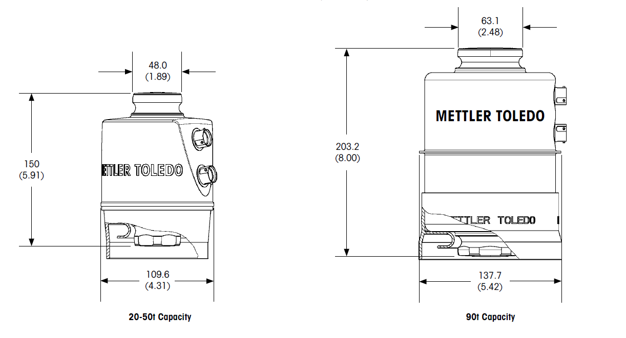
POWERCELL® PDX® Load Cell Dimensions mm (inches)


상품평
아직 상품평이 없습니다.