


설명
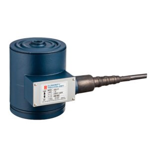
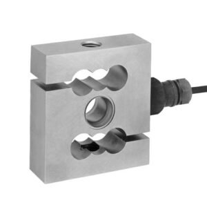
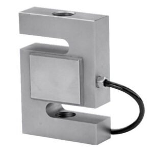
LC Tigo® Tension load cell s-type
Tension load cells from the LC Tigo series have been specially designed for weighing process vessels. Suspended mounting can better compensate for vessel movements.
Verifiable tension load cells for a variety of industrial applications
- The load cells developed in Germany guarantee the most accurate weighing results.
All load cells are verifiable according to OIML. - A comprehensive optional portfolio of transmitters, indicators and controllers ensures reliable continuous processing of the measurement signals as desired.
- For weighing processes and batching applications which require tension weighing.
- Comprehensive expertise in scale production ensures high-quality advice for individual projects.
| S-type load cell LC Tigo | |||||
| Parameters | Description | Abbr. | PR 76 N | PR 76 C3 | Unit |
| Accuracy class | 0.03 | 0.025 | % Emax | ||
| Minimum dead load | Lowest limit of specified measuring range | Emin | 0 | % Emax | |
| Maximum capacity | Highest limit of specified measuring range | Emax | 60, 125, 250, 500, 1,000, 2,000, 3,000, 5,000 |
kg | |
| Maximum usable load | Upper limit for measurements | Elim | 150 | % Emax | |
| Destructive load | Danger of mechanical destruction | Ed | 300 | % Emax | |
| Minimum LC verification | Minimum load cell verification interval, vmin = Emax/Y | Y | / | 8,333 | |
| Deadload output return | Factor for deadload output return after load (DR = 1/2*Emax /Z) | Z | / | 3,000 | |
| Rated output | Relative output at maximum capacity | Cn | 2 | mV/V | |
| Tolerance on rated output | Permissible deviation from rated output | dc | < 0.25 | %Cn | |
| Zero output signal | Load cell output signal under unloaded condition | Smin | 0 ± 2 | %Cn | |
| Repeatability error | Max. change in load cell output for repeated loading | eR | < 0.012 | %Cn | |
| Creep | Max. change of output signal at Emax during 30 min. | dcr | < 0.030 | < 0.017 | %Cn |
| Non-linearity1) | Deviation from best straight line through zero | dLin | < 0.030 | < 0.017 | %Cn |
| Hysteresis1) | Max. difference in LC output between loading and un- loading | dhy | < 0.030 | < 0.017 | %Cn |
| Temperature effect on Smin | Max. change of Smin over BT | TKSmin | < 0.028 | < 0.017 | %Cn/10K |
| Temperature effect on C1) | Max. change of C in BT | TKC | < 0.025 | < 0.011 | %Cn/10K |
| Input impedance | Between supply terminals | RLC | 400 ± 50 | Ω | |
| Output impedance | Between measuring terminals | RO | 352 ± 3 | Ω | |
| Insulation impedance | Between measuring circuit and housing at 100 VDC | RIS | >5,000 × 106 | Ω | |
| Recommended supply voltage range | To hold the specified performance | Bu | ≤ 10 | V | |
| Max. supply voltage | Continuous operation without damage | Umax | 15 | V | |
| Nominal ambient temp. range | To hold the specified performance | BT | -10 to +402) | °C | |
| Usable ambient temp. range | Continuous operation without damage | BTU | -30 to +70 | °C | |
| Storage temperature range | Without electrical and mechanical stress | BTi | -30 to +70 | °C | |
| Barometric pressure influence | Influence of barometric pressure on output | ≤ 0.004 | %Cn/kPa | ||
| Nominal deflection | Max. elastic deformation under maximum capacity | Snom | 0.2 (Emax = 60 kg … 500 kg); 0.3 (Emax = 1 t … 5 t) |
mm | |
| Sensor material | Stainless steel | ||||
| Cable length | 5 | m | |||
| IP protection class | According to EN 60529 | IP66 + IP67 | |||
1) The data for non-linearity (dLin), hysteresis (dhy) and temperature effect on C (TKC) are typical values. For OIML R60 or NTEP approved load cells, the sum of these values is within the permissible cumulative error limits.
2) 60 kg (0°C – +40°C)
| Accuracy classes and minimum verification interval, vmin | ||||||||||
| Maximum ca- pacity | Maximum number of verification intervals, nmax | 60 kg | 125 kg | 250 kg | 500 kg | 1,000 kg | 2,000 kg | 3,000 kg | 5,000 kg | Unit |
| OIML | 3,000 | 0.007 | 0.015 | 0.030 | 0.060 | 0.120 | 0.240 | 0.360 | 0.600 | kg |
| NTEP Class III Multiple | 5,000 | 0.007 | 0.015 | 0.030 | 0.060 | 0.120 | 0.240 | 0.360 | 0.600 | kg |
| NTEP Class III L Multiple | 10,000 | 0.003 | 0.007 | 0.013 | 0.025 | 0.050 | 0.100 | 0.150 | 0.250 | kg |
Technical diagrams
S-type load cell LC Tigo

| Load cell type | A | B | C | D |
| PR 76/60 kg–500 kg | 75 | 80 | M12x1.75 | 15 |
| PR 76/1 t | 75 | 80 | M20x1.5 | 15 |
| PR 76/2 t | 90 | 95 | M20x1.5 | 15 |
| PR 76/3 t–5 t | 120 | 125 | M20x1.5 | 20 |
S-type load cell LC Tigo PR 76

Circuit diagram
Load cell accessory – rod end PR 96

| Load cell type | A | B | C | D |
| PR 76/60 kg–500 kg | 155 ± 1 | 32 | 12 | 7 |
| PR 76/1 t | 203 ± 1 | 50 | 20 | 18 |
| PR 76/2 t | 218 ± 1 | 50 | 20 | 18 |
| PR 76/3 t–5 t | 238 ± 1 | 50 | 20 | 18 |
| Load cell type | E | F | G | H |
| PR 76/60 kg–500 kg | 10 | 54 | A/F19 | M12x1.75 |
| PR 76/1 t | 25 | 78 | A/F30 | M20x1.5 |
| PR 76/2 t | 25 | 78 | A/F30 | M20x1.5 |
| PR 76/3 t–5 t | 25 | 78 | A/F30 | M20x1.5 |
The stated values apply only for static and quasistatic applications
All dimensions in mm
Ex approval
Scope of validity:
LC Tigo (PR 76)
| S-type load cell LC Tigo certificates | |||
| Zone | Marking | Certificate number | For |
| 2 | II 3G Ex nA IIC T6 Gc | Manufacturer‘s declaration | All PR 76/xx |
| 22 | II 3D Ex tc IIIC T85 °C Dc | ||
Ordering information
| S-type load cell LC Tigo, C3 | |
| Type | Order number |
| PR 76/60 kg C3 | 9409 276 03060 |
| PR 76/125 kg C3 | 9409 276 03112 |
| PR 76/250 kg C3 | 9409 276 03125 |
| PR 76/500 kg C3 | 9409 276 03150 |
| PR 76/1,000 kg C3 | 9409 276 03210 |
| PR 76/2,000 kg C3 | 9409 276 03220 |
| PR 76/3,000 kg C3 | 9409 276 03230 |
| PR 76/5,000 kg C3 | 9409 276 03250 |
| S-type load cell LC Tigo, N | |
| Type | Order number |
| PR 76/60 kg N | 9409 276 01060 |
| PR 76/125 kg N | 9409 276 01112 |
| PR 76/250 kg N | 9409 276 01125 |
| PR 76/500 kg N | 9409 276 01150 |
| PR 76/1,000 kg N | 9409 276 01210 |
| PR 76/2,000 kg N | 9409 276 01220 |
| PR 76/3,000 kg N | 9409 276 01230 |
| PR 76/5,000 kg N | 9409 276 01250 |
| Load cell accessory S-type load cell LC Tigo | ||
| Type | Description | Order number |
| PR 96/00N | Ball head for PR 76 up to 500 kg | 9405 300 96001 |
| PR 96/01N | Ball head for PR 76 1 t–5 t | 9405 300 96011 |
| PR 6143/80 | Constrainer for transverse forces of <2 kN | 9405 361 43801 |
상품평
아직 상품평이 없습니다.