

설명
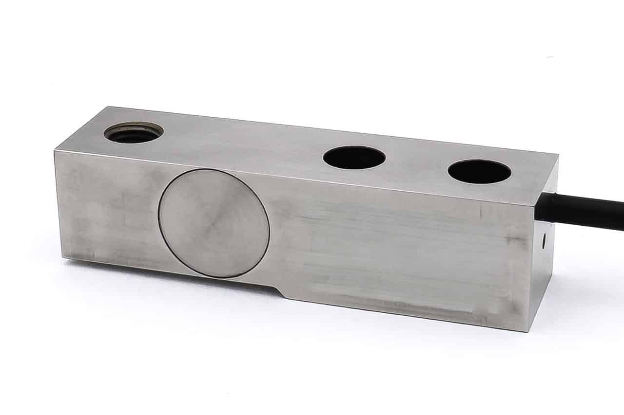
F268 Shear Beam Loadcell
Geometry: Shear strain beam for use in all process weighing applications and also engineering force measurement in compression or tension.
The F268 is ideally suited to process weighing applications which have harsh environmental requirements. The design configuration allows it to be used for installations for tank, hopper, weigh platforms or weigh bridges.
We are happy to design shear or bending beams to meet your specific requirements. Versions can be manufactured for fully compensated operation up to +250°C. Please consult our engineering department.
Specification
| Parameter | Value | Unit |
|---|---|---|
| Non-linearity – Terminal | ±0.1 | % RL |
| Hysteresis | ±0.1 | % RL |
| Creep – 20 minutes | ±0.05 | % AL |
| Repeatability | ±0.02 | % RL |
| Rated output – Rationalised | 2.0 | mV/V |
| Rationalisation tolerance (applies to single direction calibrations) | ±0.1 | % RL |
| Zero load output | ±4 | % RL |
| Temperature effect on rated output per °C | ±0.002 | % AL |
| Temperature effect on zero load output per °C | ±0.005 | % RL |
| Temperature range – Compensated | -10 to +50 | °C |
| Temperature range – Safe | -10 to +80 | °C |
| Excitation voltage – Recommended | 10 | V |
| Excitation voltage – Maximum | 10 | V |
| Bridge resistance | 350 | Ω |
| Insulation resistance – Minimum at 50Vdc | 500 | MΩ |
| Overload – Safe | 50 | % RL |
| Overload – Ultimate | 100 | % RL |
| Sealing | IP65 |
Order Codes
| Code | Description |
|---|---|
| F268CFR0HN | Compression, IP65, rationalised |
| F268UFR0HN | Bi-directional, IP65, rationalised |
| F268TFR0HN | Tension, IP65, rationalised |
Structural Stiffness
| Range (kN) | Stiffness (N/m) |
|---|---|
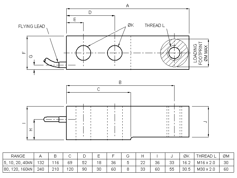
| 5 | 1.3 x 10⁸ |
| 10 | 2.0 x 10⁸ |
| 20 | 3.3 x 10⁸ |
| 40 | 6.6 x 10⁸ |
| 80 | 8.5 x 10⁸ |
| 120 | 1.3 x 10⁹ |
| 160 | 1.7 x 10⁹ |
Notes
- AL = Applied load.
- RL = Rated load.
- Temperature coefficients apply over the compensated range.
Connections
For ranges up to 4tonnef the loadcell is fitted with 2 metres of PVC insulated 4 core screened cable type 7-2-4C. Ranges above 4 tonnefs are fitted with 16-2-4C cable.
Excitation + = Red, Excitation – = Blue, Signal + = Yellow, Signal – = Green, Screen = Orange.
Reverse the signal connections to obtain a positive signal in tension mode. The screen is not connected to the loadcell body.

상품평
아직 상품평이 없습니다.