


설명
VDW Self-Centering Pressure Load Cell
APPLICATION
Acting as a measuring transducer, the load cell converts the mechanical input variable (load) into the electrical output variable (voltage).
The VDW has been consistently optimized for use in vehicle scales.
- The design of the cell as a self-straightening stabilizer link keeps transverse forces away, even if the bridge is significantly displaced horizontally.
- The design allows rapid and cost-effective assembly without expensive mounting parts.
- Matching accessories and fitting aids simplify installation.
CONSTRUCTION
Hermetically sealed thanks to laser welding (IP68)
- High corrosion protection through the use of rustproof materials, including high-grade steel cable screw connections
- Built-in over-voltage protection
- All electrical components are located inside the load cell and are therefore optimally protected
- Laser-welded construction, protection class IP68 (1 m immersion depth / 100 hr) or IP69K (steam jet cleaning)
FUNCTION
High measuring sensitivity
- High reproducibility
- High long-term stability and consistently high accuracy over time
- Characteristic value and output impedance of the VDW are matched so that corner-load comparison in multiple-cell scales is generally unnecessary
- The optimized screening concept (no conductive connection between cable screen and load cell body) provides excellent protection against electromagnetic interference
Technical Data
| Rated Capacity | Emax | 33t / 44t | Reference | |||
| Accuracy Class: | C3 | |||||
| Nominal Characteristic Value | Cn | 2.2 mV/V ± 0.5% *) | ||||
| Combined Errors | Fcomb | 0.02 % | Cn | |||
| Zero-Signal Return After Loading (30m) |
Fdr |
± 0.12 % |
Cn |
|||
| Creeping Under Load (30 min) |
Fcr |
± 0.017 % |
Cn |
|||
| Temperature Coefficient | TK0 | ± 0.014 % | Cn, Btn | |||
| of the Zero Signal per 10 K | ± 0.04 % | Cn, Btu | ||||
| Temperature Coefficient | TKc | ± 0.008 % | Cn, Btn | |||
| of the Characteristic Value per 10 K | ± 0.025 % | Cn, Btu | ||||
| Max. Permissible Number of Legal for Trade Scale Intervals |
nLC |
3000 | ||||
| Smallest Scale Interval | Vmin | Emax/10000 | ||||
| Max. Application Area | Bamax | Bamax = Emax | ||||
| Input Resistance | Re | 700 W ± 3% | Tr | |||
| Output Resistance | Ra | 706 W ± 0.5% *) | Tr | |||
| Zero Signal | S0 | ± 1% | Cn | |||
| Max. Supply Voltage | Usmax | 12V +10% | ||||
| Nominal Temperature Range | Btn | -10°C to +40°C | ||||
| Operating Temperature Range | Btu | -30°C to +70°C | ||||
| Storage Temperature Range | Bts | -50°C to +85°C | ||||
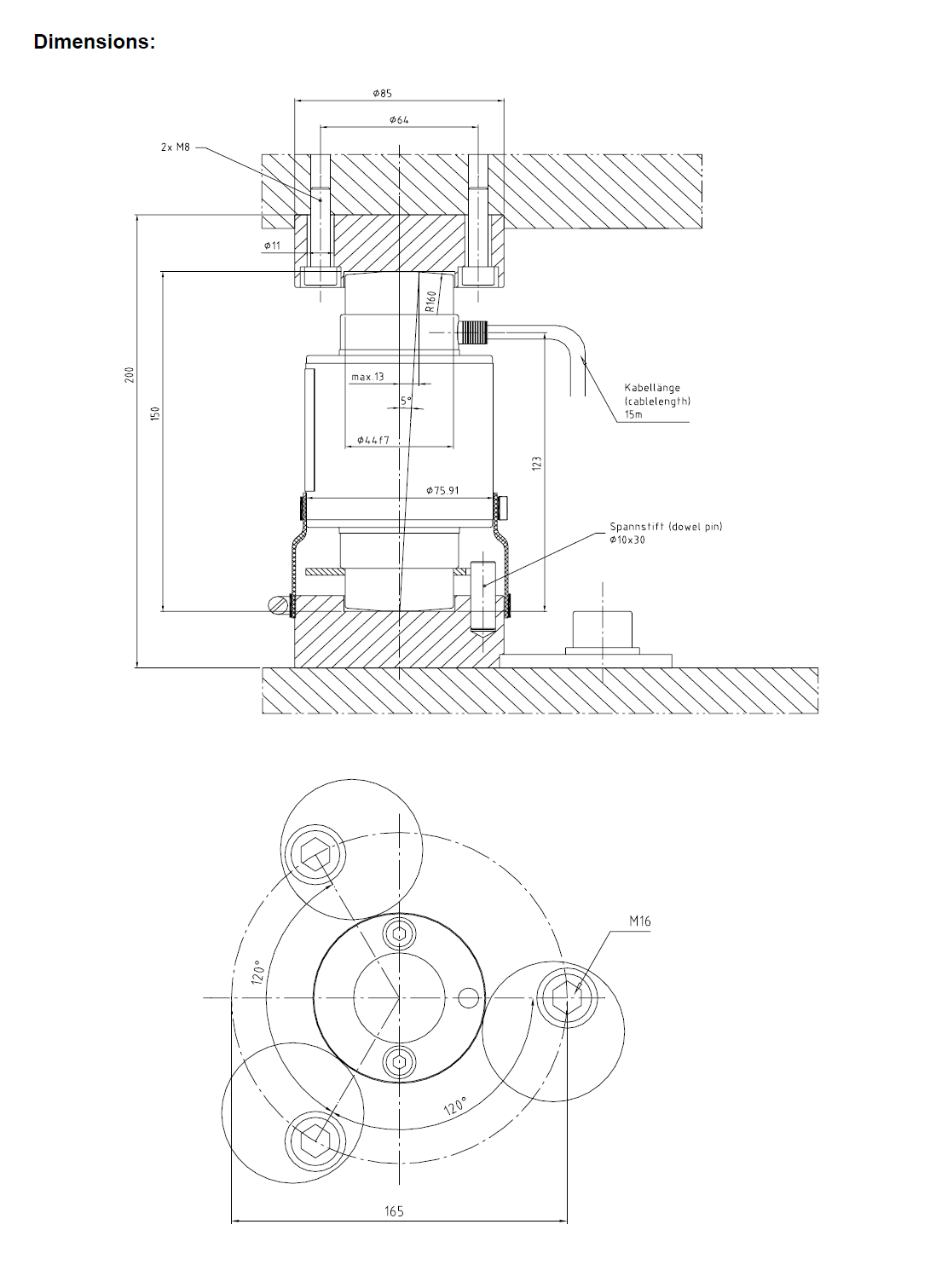
| Permissible Angle Error | a | 5° | ||||
| Permissible Horizontal Displace- ment | Smax | 13mm | ||||
| Restoring Force | Fr | 0.76% / 0.94% per mm displacement | E | |||
| Nominal Measuring Displacement | 0.8mm / 0.9mm | Emax | ||||
| Limit Load | El | 45t / 60t | ||||
| Breaking Load | Ld | 100t / 125t | ||||
| Vibrational Loading (as per DIN 50100) | 70% Emax. Peak load may not exceed the load Emax | |||||
| Protection Class | IP 68 (1m; 100hr); IP 69K | |||||
|
Cable Specification |
TPE (grey) Æ 6,5 mm, silicone- and halogen-free,
-30°C to +150°C; length 15m |
|||||
|
Connection Assignment |
black: grey: red: | input + sense + output + | / blue:
/ green: / white: |
input – sense – output – | ||
| Material | Stainless steel | |||||
| Weight | 2.3 kg | |||||
*) Characteristic value and output impedance of the VDW are compared to each other such that the corner-load comparison for a multiple-cell scales generally becomes redundant – assuming that the mechanics of the scales can guarantee a clean, reproducible load distribution across the sensors.
Order Numbers
Design
VDW 33t, C3
V07xxxx.B01


상품평
아직 상품평이 없습니다.