


설명
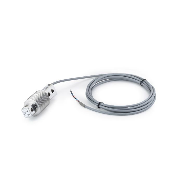
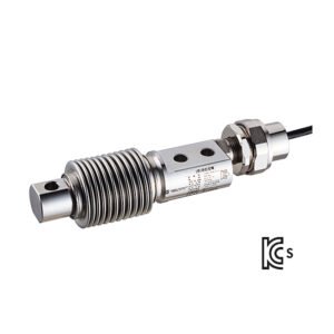
SENSiQ Weighbeam WB
APPLICATION
- Ladle turret scale
- Ladle transfer car
- Scrap basket, roller, and tundish scales
- Silo and bin weighers
FUNCTION
- Simple and cost-effective installation through direct bolted joint with the connecting structure without moving parts
- No additional straps or hold down bolts required
- High functional safety and availability, even with frequently unavoidable impact loads and constraining forces
- For maintenance-free scales operated under harsh conditions
CONSTRUCTION
- Compact, flat design
- From WB 50 t: Fit head for form-locking take-up of lateral forces
- Plug connection, also available as hinged plug outlet (WB 40 t – WB 600 t)
- Transfer of high disturbance forces and torques with minimum measuring value interference
- High long-term stability
- High reproducibility
- Separate installation of Weighbeam and connecting cable possible
- Cable change without problems
- Connection dimensions and electrical data are compatible with the earlier design of the weighbeam DWB according to data sheet BV-D2059 and BV-D2058
Operating Principle
WB 11,5 t … 600 t

Installation dimensions WB 11,5 t … 25 t as hinged plug outlet

Fitting dimension when connecting with a straight plug connection
WB 40 t

WB 50 t … 200 t
* Another 15 mm are needed for isolating the plug connection.
[mm]
| Design | A | B | C | D | F | G | H | I | K | L | M (**) | N | O | P | R | S | T |
| WB 50 t | 450 | 120 | 130 | 105 | 398 | 68 | 75 | 40 | 80 | 110 | 26 (M24) | M20 | 62 | 45 | 340 | 25,5 | 57 |
| WB 100 t | 500 | 140 | 143 | 118 | 444 | 80 | 90 | 44 | 90 | 130 | 30 (M27) | M24 | 74 | 54 | 370 | 28,5 | 63 |
| WB 150 t | 560 | 160 | 158 | 133 | 500 | 94 | 102 | 44 | 90 | 150 | 33 (M30) | M24 | 74 | 66 | 410 | 32 | 69 |
| WB 200 t | 620 | 180 | 175 | 150 | 560 | 114 | 110 | 44 | 90 | 160 | 33 (M30) | M24 | 80 | 75 | 450 | 32 | 76 |
(**) Screw size
WB 600 t

* Another 15 mm are needed for isolating the plug connection.
[mm]
| Design | A | B | C | D | E | F | G | H | I | K | M (**) | N | O | P | R | S | T |
| WB 600 t | 800 | 255 | 330 | 270 | 610 | 740 | 170 | 170 | 100 | 210 | 32 (M30) | M42 | 160 | 137.5 | 550 | 32 | 85.5 |
(**) Screw size
Fitting dimension when connecting with hinged plug connection
WB 40 t … 600 t

| Design | A | B | C | E | F | G | L *) | O | R | S | P |
| WB 40 t | 450 | 110 | 105 | 96 | 45 | 57 | 0°/180° | 80 | 47 | 76 | 10 |
| WB 50 t | 450 | 120 | 130 | 91 | 45 | 57 | 0°/180° | 80 | 42 | 71 | 10 |
| WB 100 t | 500 | 140 | 143 | 85 | 54 | 63 | 0°/180° | 89 | 36 | 65 | 19 |
| WB 150 t | 560 | 160 | 158 | 79 | 66 | 69 | 0°/180° | 101 | 30 | 59 | 31 |
| WB 200 t | 620 | 180 | 175 | 74 | 75 | 76 | 0°/180° | 110 | 25 | 54 | 40 |
| WB 600 t | 800 | 255 | 330 | 64 | 137.5 | 85.5 | 0°/180° | 172.5 | 15 | 44 | 102.5 |
NOTES
- *) Cable outlet possible on both sides
- 0°: Cable outlet on the right
- 180°: Cable outlet on the left
- Standard: Cable outlet on the right
Technical Data
| WB
11,5 t |
WB
15 t |
WB
25 t |
WB
40 t |
WB
50 t |
WB
100 t |
WB
150 t |
WB
200 t |
WB
600 t |
Ref | ||
| Accuracy class1) | – | D0,7 | |||||||||
| Nominal load | Emax | 11,5 t | 15 t | 25 t | 40 t | 50 t | 100 t | 150 t | 200 t | 600 t | |
| Limit load (with Lq = 0.15 x LI) Limit load = max. safe load |
LI |
23 t | 26 t | 35 t | 100 t | 120 t | 210 t | 290 t | 360 t | 1000 t | |
| Breaking load
(with Lq = 0.15 x Ld) |
Ld |
35 t | 38 t | 40 t | 160 t | 200 t | 350 t | 480 t | 600 t | 1200 t | |
| Max. permitted lateral load | Lq, max | 15 t | 18 t | 25 t | 40 t | 50 t | 85 t | 120 t | 150 t | 400 t | |
| Nominal characteristic value
± 0,2 % |
Cn |
0,90
mV/V |
1,16
mV/V |
1,40
mV/V |
0,95
mV / V |
1,08
mV / V |
1,38
mV / V |
1,57
mV / V |
1,63
mV / V |
1,40
mV/V |
Emax |
| Compound error | Fcomb | ±0,2 % 2) | ±0,1 % 2) | ±0,07 % 2) | ±0,1 % 2) | Cn | |||||
| Creepage under load
(30 min) |
Fcr |
±0,05 % |
Cn |
||||||||
| max. admissible no. of legal- for-trade scale intervals1) |
nLC |
– | 700 | ||||||||
| Smallest scale interval1) | Vmin | – | Emax / 700 | ||||||||
| Input resistance | Re | 694 W ±8 W | Tr | ||||||||
| Output resistance | Ra | 700 W ±4 W | Tr | ||||||||
| Ref- supply voltage | Usref | 10 V | |||||||||
| Max. supply voltage | Usmax | 36 V | |||||||||
| Nominal temperature | Btn | -10 °C … +100 °C | |||||||||
| Operating temperature (and storage temperature range) |
Btu |
-40 °C … +180 °C |
|||||||||
| Temperature | Tr | +22 °C | |||||||||
| Temperature coefficient of
the zero signal |
TKo | ±0,05 % / 10 K 2) | Cn in Btu | ||||||||
| Temperature coefficient of
the characteristic value |
TKc | ±0,05 % / 10 K 2) | ±0,03 % / 10 K 2) | ||||||||
| Self-weight | me | 18 kg | 39 kg | 40 kg | 55 kg | 85 kg | 120 kg | 400 kg | |||
| Surface | galvanized | ||||||||||
| Protection class | IP67 | IP68 | |||||||||
|
Cable specification |
The weighbeam has a plug connection.
A separate, shielded cable (Ø 8.5 mm x 15 m) is also supplied with suitable plug socket.
The following applies to the cable: Silicon cable, bend radius: > 40 mm; temperature range: -50 °C …+180 °C |
||||||||||
|
Cable connection allocation |
Black: input + (82) Blue: Input – (81)
Red: Output + (28) White: Output – (27) Yellow: sense + (82.1) Green: sense – (81.1) Black/yellow: shielding Purple/brown: temperature sensor Pt100
(Not connected sense line – lines have to be insulated) |
||||||||||
1) for information only
2) in isothermic state
Requirements of the Quality of both Contact Surfaces
WB 11,5 t … 40 t

WB 50 t … 600 t
▪ Material selection “A”: Construction steel is used of at least S355 grade must be used.
▪ Operating thickness “B”: This depends on the stiffness of the overall construction. The operating thickness of the connect surfaces must be at least 40% of the the weighbeam height.
▪ Surface quality “C”: The average peak-to-valley height required of the contact surfaces is 6.3 μm.
▪ Flatness “D”: The maximum permissible flatness tolerance of each contact surface is 0.05 mm.
▪ Angle error to the vertical axis “E”: The permitted maximum value for the angle deviation of the contact surface to the vertical axis is ± 2° in both planes.
▪ Plane parallelism “F”: The upper and lower contact surfaces to the weighbeam must be plan parallel to each other within at least 0.1 mm.
Order Numbers
| Design | Order number with straight plug outlet (see drawing above) | Order number with lateral plug outlet on the right
(cf. page 7) *) |
|
| WB11,5 t | not available | V711375.B73 | |
| WB | 15 t | not available | V711375.B83 |
| WB | 25 t | not available | V711375.B93 |
| WB | 40 t | V711375.B03 | V758596.B01 |
| WB | 50 t | V711375.B13 | V758596.B11 |
| WB 100 t | V711375.B23 | V758596.B21 | |
| WB 150 t | V711375.B33 | V758596.B31 | |
| WB 200 t | V711375.B43 | V758596.B41 | |
| WB 600 t | V711375.B53 | V758596.B51 | |
| Spare part: Connecting cable
15 m with plug connection |
V090162.B01 | ||
| High-temperature cable:
15 m with plug socket
Constant operation of the cable is permitted at – 65 °C … +300 °C.
Operation is permitted at +700 °C for a period of up to 90 minutes. |
V090162.B07 | ||
*) Plug outlet in the other direction possible on request
상품평
아직 상품평이 없습니다.