

설명
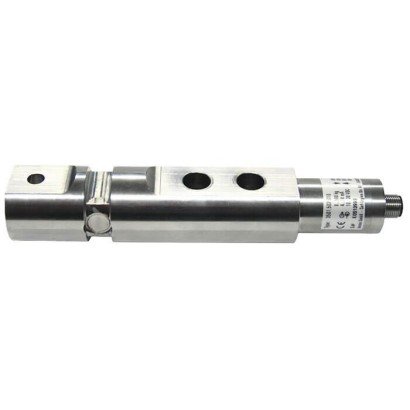
Models F3301, F33C1, F33S1 Shear beam
With thin-film technology up to 100 kN
Shear beams of models F33x1 are suitable for static and dynamic measuring requirements. They serve for determining shear forces in diverse fields of application.
The shear beams are very often used in industrial weighing technology as well as in the areas of special machinery construction and production automation. They are also used in laboratory technology and the processindustry to determine torque.
The corresponding technical and regional approvals of these force transducers are, of course, available as options.
The shear beams are made of high-strength, corrosion-resistant 1.4542 stainless steel, the properties of which are particularly well-suited to the areas of application of the shear beams.
As output signals, the common active current and voltage outputs are available (4 … 20 mA, 0 … 10 V). Redundant output signals and CANopen® protocols are possible.
The shear beams can be integrated into a certified WIKA overload protection with model ELMS1 (DIN EN ISO 13849-1 with PL d/Cat. 3).
Specifications
| Technical Data | Specification |
|---|---|
| Electrical Connection | Circular connector M12 × 1 (4- or 5-pin)CANopen®, M12 × 1 (5-pin)MIL connector2-connector version M12 × 1 (4-pin) |
| Output Signal Options | 4–20 mA (2-wire)4–20 mA (3-wire)2 × 4–20 mA redundant0–10 V DC (3-wire)2 × 0–10 V redundantCANopen® |
| CANopen® Protocol | CiA® 301, device profile CiA® 404LSS (CiA® 305), Sync/AsyncNode/Lifeguarding, heartbeatZero/span adjustable ±10 % via object directory |
| Redundant Option | 4–20 mA / 20–4 mA opposing |
| Functional Safety Version | WIKA overload protection ELMS1DIN EN ISO 13849-1, PL d / Cat. 3Machinery Directive 2006/42/EC |
| Current Consumption | 4–20 mA (2-wire): signal current4–20 mA (3-wire): < 8 mAVoltage output: < 8 mACANopen®: < 1 W |
| Supply Voltage (UB) | DC 9–36 V (current output)DC 13–36 V (voltage output)DC 9–36 V (CANopen®)DC 10–30 V (current output version) |
| Load | ≤ (UB – 10 V) / 0.024 A (current output)> 10 kΩ (voltage output)Channel 1: ≤ (UB – 10 V) / 0.020 AChannel 2: ≤ (UB – 7 V) / 0.020 A |
| Response Time | ≤ 2 ms (10–90 % Fnom) |
| Ingress Protection (IEC/EN 60529) | Unplugged: IP66 / IP67Plugged: IP68 / IP69 / IP69K |
| Electrical Protection | Reverse polarity protectionOvervoltage protectionShort-circuit protection |
| Vibration Resistance | 20 g, 100 h, 50 … 150 HzIn accordance with DIN EN 60068-2-6 |
| Shock Resistance | In accordance with DIN EN 60068-2-27 |
| Immunity (EMC) | In accordance with DIN EN 61326-1 / DIN EN 61326-2-3 |
| EMC Options | EMC-strengthened versions available |
1) Relative linearity error is specified in accordance with Directive VDI/VDE/DKD 2638 chapter 3.2.6.
2) Protocol in accordance with CiA® 301, device profile CiA® 404, communication service LSS (CiA® 305).
CANopen® and CiA® are registered community trademarks of CAN® in Automation e. V.
3) Further response times possible on request.
Specifications
| Basic informations | Model F3301 and F33C1 with UL | Model F33S1 | |||||
| Standard | In accordance with guidline VDI/VDE/DKD 2638 | ||||||
| Rated force Fnom kN | 2 | 5 | 10 | 20 | 30 | 50 | 100 |
| Rated force Fnom lbf | 449.6 | 1,124 | 2,248 | 4,496 | 6,744 | 11,240 | 22,481 |
| Relative linearity error dlin1) | ±1 % Fnom | ||||||
| Relative reversibility error v | < 0.1 % Fnom | ||||||
| Relative creep | 0.05 % Fnom | ||||||
| Temperature effect on | |||||||
| the characteristic value TKc | 0.2 % Fnom / 10 K | ||||||
| the zero signal TK0 | 0.2 % Fnom / 10 K | ||||||
| Force limit FL | 150 % Fnom | ||||||
| Breaking force FB | |||||||
| 2 kN / 20 kN … 100 kN [449.6 lbf / 4,496 lbf … 22,481 lbf] | 300 % Fnom | ||||||
| 10 kN [2,248 lbf] | 270 % Fnom | ||||||
| Permissible vibration loading Frb | ±50 % Fnom | ||||||
| Rated displacement (typical) snom | |||||||
| < 10 kN [2,248 lbf] | < 0.02 mm [< 0.00079 in] | ||||||
| < 100 kN [22,481 lbf] | < 0.2 mm [< 0.0079 in] | ||||||
| Material of the measuring body | ■ Corrosion-resistant stainless steel, 1.4542, ultrasound-tested 3.1 material ■ Version with 3.2 material available |
||||||
| Rated temperature BT, nom | -20 … +80 °C [-4 … +176 °F] | ||||||
| Operating temperature BT, G | ■ -30 … +80 °C [-22 … +176 °F] ■ -40 … +80 °C [-40 … +176 °F] |
-30 … +80 °C [-22 … +176 °F] | |||||
| Storage temperature BT, S | -40 … +85 °C [-40 … +185 °F] | ||||||
| Electrical connection | ■ Circular connector M12 x 1, 4- or 5-pin ■ CANopen®, Circular connector M12 x 1, 5-pin ■ MIL-connector |
■ 2-connector version M12 x 1, 4-pin ■ MIL-connector |
|||||
| Output signal (rated characteristic value) Cnom | ■ 4 … 20 mA, 2-wire ■ 4 … 20 mA, 3-wire ■ 2 x 4 … 20 mA redundant ■ DC 0 … 10 V, 3-wire ■ 2 x DC 0 … 10 V redundant ■ CANopen® Protocol in accordance with CiA® 301, device profile CiA® 404, communication services LSS (CiA® 305), configuration of the instrument address and baud rate Sync/ Async, Node/Lifeguarding, heartbeat; zero point and span adjustable by ±10 % via entries in the object directory 2) |
Redundant, opposing 4 … 20 mA / 20 … 4 mA Version in accordance with requirements for functional safety per machinery directive 2006/42/EC as WIKA overload protection with model ELMS1 (DIN EN ISO 13849-1 with PL d/cat. 3). | |||||
| Current/power consumption | ■ Current output 4 … 20 mA, 2-wire: Signal current ■ Current output 4 … 20 mA, 3-wire: < 8 mA ■ Voltage output: < 8 mA ■ CANopen®: <1 W |
Current output 4 … 20 mA: Signal current | |||||
| Supply voltage UB | ■ DC 9 … 36 V for current output ■ DC 13 … 36 V for voltage output ■ DC 9 … 36 V for CANopen® |
DC 10 … 30 V for current output | |||||
| Load | ■ ≤ (UB – 10 V) / 0.024 A for current output ■ > 10 kΩ for voltage output |
■ ≤ (UB – 10 V) / 0.020 A (channel 1) for current output ■ ≤ (UB – 7 V) / 0.020 A (channel 2) for current output |
|||||
| Response time | ≤ 2 ms (within 10 … 90 % Fnom) 3) | ||||||
| Ingress protection (per IEC/EN 60529) | |||||||
| Unplugged state | IP66, IP67 | IP67 | |||||
| Plugged-in state | IP68, IP69, IP69K | ||||||
| Basic informations | Model F3301 and F33C1 with UL | Model F33S1 |
| Electrical protection | Reverse polarity, overvoltage and short-circuit protection | |
| Vibration resistance | 20 g, 100 h, 50 … 150 Hz per DIN EN 60068-2-6 | |
| Shock resistance | DIN EN 60068-2-27 | |
| Immunity | ■ In accordance with DIN EN 61326-1/DIN EN 61326-2-3 ■ EMC-strengthened versions |
|
- Relative linearity error is specified in accordance with Directive VDI/VDE/DKD 2638 chapter 2.6.
- Protocol in accordance with CiA® 301, device profile CiA® 404, communication service LSS (CiA® 305). CANopen® and CiA® are registered community trademarks of CAN® in Automation e.
- Further response times possible on
| Basic informations | Model F33C1 ATEX/IECEx EX ib 1) | Model F3301 Signal jump | |||||
| Standard | In accordance with guidline VDI/VDE/DKD 2638 | ||||||
| Rated force Fnom kN | 2 | 5 | 10 | 20 | 30 | 50 | 100 |
| Rated force Fnom lbf | 449.6 | 1,124 | 2,248 | 4,496 | 6,744 | 11,240 | 22,481 |
| Relative linearity error dlin 2) | ±1 % Fnom | ||||||
| Relative reversibility error v | < 0.1 % Fnom | ||||||
| Relative creep | 0.05 % Fnom | ||||||
| Temperature effect on | |||||||
| the characteristic value TKc | 0.2 % Fnom / 10 K | ||||||
| the zero signal TK0 | 0.2 % Fnom / 10 K | ||||||
| Force limit FL | 150 % Fnom | ||||||
| Breaking force FB | |||||||
| 2 kN / 20 kN … 100 kN [449.6 lbf / 4,496 lbf … 22,481 lbf] | 300 % Fnom | ||||||
| 10 kN [2,248 lbf] | 270 % Fnom | ||||||
| Permissible vibration loading Frb | ±50 % Fnom | ||||||
| Rated displacement (typical) snom | |||||||
| < 10 kN [2,248 lbf] | < 0.02 mm [< 0.00079 in] | ||||||
| < 100 kN [22,481 lbf] | < 0.2 mm [< 0.0079 in] | ||||||
| Material of the measuring body | ■ Corrosion-resistant stainless steel, 1.4542, ultrasound-tested 3.1 material ■ Version with 3.2 material available | ||||||
| Rated temperature BT, nom | -20 … +80 °C [-4 … +176 °F] | ||||||
| Operating temperature BT, G | Ex II 2G Ex ib IIC T4 Gb -25 °C < Tamb < +85 °C Ex II 2G Ex ib IIC T3 Gb -25 °C < Tamb < +100 °C Ex I M2 Ex ib I Mb -25 °C < Tamb < +85 °C Ex II 2G Ex ib IIC T4 Gb -40 °C < Tamb < +85 °C Ex I M2 Ex ib I Mb | -30 … +80 °C [-22 … +176 °F] | |||||
| Storage temperature BT, S | -40 … +85 °C [-40 … +185 °F] | ||||||
| Electrical connection | ■ Circular connector M12 x 1, 4-pin ■ MIL-connector ■ Cable gland | ||||||
| Output signal (rated characteristic value) Cnom | 4 … 20 mA, 2-wire | ■ 4 … 16 mA, 2-wire 3) ■ DC 2 … 8 V, 3-wire 3) | |||||
| Current/power consumption | Current output 4 … 20 mA 2-wire: Signal current | ■ Current output 4 … 20 mA 2-wire: signal current ■ Current output 4 … 20 mA 3-wire: < 8 mA ■ Voltage output: < 8 mA | |||||
| Supply voltage UB | DC 10 … 30 V for current output | ■ DC 10 … 30 V for current output ■ DC 14 … 30 V for voltage output | |||||
| Basic informations | Model F33C1 ATEX/IECEx EX ib 1) | Model F3301 Signal jump |
| Load | ■ ≤ (UB – 10 V) / 0.024 A for current output ■ > 10 kΩ for voltage output | |
| Response time | ≤ 2 ms (within 10 … 90 % Fnom) 4) | |
| Ingress protection (per IEC/EN 60529) | IP67 | |
| Electrical protection | Reverse polarity, overvoltage and short-circuit protection | |
| Vibration resistance | 20 g, 100 h, 50 … 150 Hz per DIN EN 60068-2-6 | |
| Shock resistance | DIN EN 60068-2-27 | |
| Immunity | ■ In accordance with DIN EN 61326-1/DIN EN 61326-2-3 ■ EMC-strengthened versions | |
1) The shear beam with ignition protection type “ib” should only be powered using galvanically isolated repeater power supplies.
Suitable repeater power supplies can be offered as an option, e.g. order number: 14255084.
2) Relative linearity error is specified in accordance with Directive VDI/VDE/DKD 2638 chapter 3.2.6
3) Further signal jumps are realisable on request.
4) Further response times possible on request.
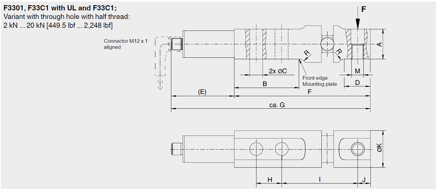
Dimensions in mm [in]
| Rated force in kN | Dimensions in mm | ||||||||||||
| A-0.1 | B | Ø C | D | E | F | approx. G | H | I | J | Ø K | M | R | |
| 2; 5; 10; 20 | 30.1 | 64.8 | 13 | 25.4 | 63 | 136.4 | 199 | 25.4 | 76.2 | 12.7 | 37 | M12 | 8 |
| Rated force in lbf | Dimensions in Inch | ||||||||||||
| A-0.04 | B | Ø C | D | E | F | approx. G | H | I | J | Ø K | M | R | |
| 449.6; 1,124; 2,248; 4,496 | 1.185 | 2.55 | 0.51 | 1 | 2.48 | 5.37 | 7.83 | 1 | 3 | 0.5 | 1.456 | M12 | 0.315 |

상품평
아직 상품평이 없습니다.