

설명
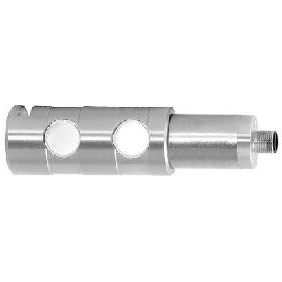
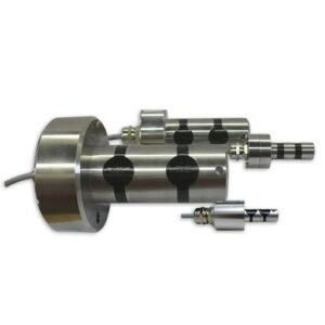
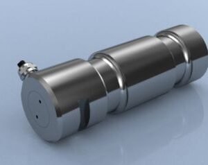
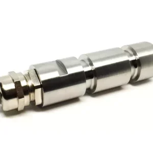
Models F5301, F53C1 Load pin
Load pins are used for static and dynamic measuring tasks as replacements for non-measuring bolts. They are used to determine tension and/or compression forces.
Load pins of this series are mainly used in hoists and crane systems. They also serve as reliable sensors in industrial weighing technology as well as in the field of production automation, mechanical and plant engineering, where they are used in particular in pulleys, cable winches, fork or roller bearings. The load pins have also proven themselves in the chemical and petrochemical industries.
The corresponding technical and regional approvals of these force transducers are, of course, available as options.
Model F5301 and F53C1 load pins are made of high-strength, corrosion-resistant 1.4542 stainless steel, the properties of which are particularly well-suited to the application areas of the load pins.
As output signals, the common active current and voltage outputs are available (4 … 20 mA, 0 … 10 V).
Redundant output signals and CANopen® protocols are also possible.
Specifications per VDI/VDE/DKD 2638
| Model | F5301 and F53C1 with UL approval | ||||||
| Rated force Fnom kN | 5 | 10 | 20 | 30 | 50 | 100 | 200 |
| Rated force Fnom lbf | 1,124 | 2,248 | 4,496 | 6,744 | 11,240 | 22,481 | 44,962 |
| Relative linearity error dlin 1) | ±1 % Fnom | ||||||
| Relative repeatability error in unchanged mounting position brg | ±0.2 % Fnom | ||||||
| Temperature effect on | |||||||
| the characteristic value TKc | 0.2 % Fnom / 10 K | ||||||
| the zero signal TK0 | 0.2 % Fnom / 10 K | ||||||
| Force limit FL | 150 % Fnom | ||||||
| Breaking force FB | 300 % Fnom | ||||||
| Transverse force effect dQ (signal at 100 % Fnom under 90°) | ±5 % Fnom | ||||||
| Rated displacement (typical) snom | < 0.1 mm [< 0.004 in] | ||||||
| Material of the measuring body | ■ Corrosion-resistant stainless steel, 1.4542, ultrasound-tested 3.1 material ■ With 3.2 material | ||||||
| Rated temperature BT, nom | -20 … +80 °C [-4 … +176 °F] | ||||||
| Service temperature BT, G | -30 … +80 °C [-22 … +176 °F] | ||||||
| Storage temperature BT, S | -40 … +85 °C [-40 … +185 °F] | ||||||
| Electrical connection | ■ Circular connector M12 x 1, 5-pin ■ CANopen® M12 x 1, 5-pin circular connector |
||||||
| Output signal (rated characteristic value) Cnom | ■ 4 … 20 mA, 2-wire ■ 4 … 20 mA, 3-wire ■ 2 x 4 … 20 mA ■ DC 0 … 10 V, 3-wire ■ 2 x DC 0 … 10 V ■ CANopen® Protocol in accordance with CiA® 301, device profile CiA® 404, communication services LSS (CiA® 305), configuration of the instrument address and baud rate Sync/Async, Node/ Lifeguarding, heartbeat; zero and span ±10 % adjustable via entries in the object directory 2) |
||||||
| Current/power consumption | ■ Current output 4 … 20 mA 2-wire: signal current ■ Current output 4 … 20 mA 3-wire: < 8 mA ■ Voltage output: < 8 mA ■ CANopen®: <1 W |
||||||
| Supply voltage UB | ■ DC 9 … 36 V for current output ■ DC 13 … 36 V for voltage output ■ DC 9 … 36 V for CANopen® |
||||||
| Load | ■ ≤ (UB – 10 V) / 0.024 A for current output ■ > 10 kΩ for voltage output |
||||||
| Reponse time | ≤ 2 ms (within 10 … 90 % Fnom) 3) | ||||||
| Ingress protection (per IEC/EN 60529) | |||||||
| Unplugged state | IP66, IP67 | ||||||
| Plugged-in state | IP68, IP69, IP69K | ||||||
| Electrical protection | Reverse polarity protection, overvoltage and short-circuit resistance | ||||||
| Vibration resistance | 20g, 100 h, 50 … 150 Hz (in accordance with DIN EN 60068-2-6) | ||||||
| Shock resistance | In accordance with DIN EN 60068-2-27 | ||||||
| Immunity | In accordance with DIN EN 61326-1/DIN EN 61326-2-3 (optional EMC-strengthened versions) | ||||||
| Intended use | Indoor and outdoor use, typically at altitudes of up to 2,500 m [8,202.5 ft] above sea level. | ||||||
1) Relative linearity error is specified in accordance with Directive VDI/VDE/DKD 2638 chapter 3.2.6.
2) Protocol in accordance with CiA® 301, device profile CiA® 404, communication service LSS (CiA® 305).
CANopen® and CiA® are registered community trademarks of CAN® in Automation e. V.
3) Further reponse times possible on request.
Specifications per VDI/VDE/DKD 2638
| Model | F53C1 for ATEX/IECEx EX ib 1) | F5301 for signal jump | |||||||
| Rated force Fnom kN | 5 | 10 | 20 | 30 | 50 | 100 | 200 | ||
| Rated force Fnom lbf | 1.124 | 2.248 | 4.496 | 6.744 | 11.240 | 22.481 | 44.962 | ||
| Relative linearity error dlin 2) | ±1 % Fnom | ||||||||
| Relative repeatability error in unchanged mounting position brg | ±0.2 % Fnom | ||||||||
| Temperature effect on | |||||||||
| the characteristic value TKc | 0.2 % Fnom / 10 K | ||||||||
| the zero signal TK0 | 0.2 % Fnom / 10 K | ||||||||
| Force limit FL | 150 % Fnom | ||||||||
| Breaking force FB | 300 % Fnom | ||||||||
| Transverse force effect dQ (signal at 100 % Fnom under 90°) | ±5 % Fnom | ||||||||
| Rated displacement (typical) snom | < 0.1 mm [< 0.004 in] | ||||||||
| Material of the measuring body | ■ Corrosion-resistant stainless steel, 1.4542, ultrasound-tested 3.1 material ■ With 3.2 material |
||||||||
| Rated temperature BT, nom | -20 … +80 °C [-4 … +176 °F] | ||||||||
| Service temperature BT, G | Ex II 2G Ex ib IIC T4 Gb -25 °C < Tamb < +85 °C Ex II 2G Ex ib IIC T3 Gb -25 °C < Tamb < +100 °C Ex I M2 Ex ib I Mb -25 °C < Tamb < +85 °C Ex II 2G Ex ib IIC T4 Gb -40 °C < Tamb < +85 °C Ex I M2 Ex ib I Mb | -30 … +80 °C [-22 … +176 °F] | |||||||
| Storage temperature BT, S | -40 … +85 °C [-40 … +185 °F] | ||||||||
| Electrical connection | ■ M12 x 1 circular connector, 4-pin ■ Cable gland | ||||||||
| Output signal (rated characteristic value) Cnom | ■ 4 … 20 mA, 2-wire | ■ 4 … 16 mA, 2-wire 3) ■ DC 2 … 8 V, 3-wire 3) |
|||||||
| Current/power consumption | ■ Current output 4 … 20 mA 2-wire: signal current | ■ Current output 4 … 20 mA 2-wire: signal current ■ Current output 4 … 20 mA 3-wire: < 8 mA ■ Voltage output: < 8 mA |
|||||||
| Supply voltage UB | DC 10 … 30 V for current output | ■ DC 9 … 36 V for current output ■ DC 13 … 36 V for voltage output |
|||||||
| Load | ■ ≤ (UB – 10 V) / 0.024 A for current output ■ > 10 kΩ for voltage output | ||||||||
| Reponse time | ≤ 2 ms (within 10 … 90 % Fnom) 4) | ||||||||
| Ingress protection (per IEC/EN 60529) | |||||||||
| Unplugged state | IP67 | IP66, IP67 | |||||||
| Plugged-in state | IP68, IP69, IP69K | ||||||||
| Electrical protection | Reverse polarity protection, overvoltage and short-circuit resistance | ||||||||
| Vibration resistance | 20g, 100 h, 50 … 150 Hz (in accordance with DIN EN 60068-2-6) | ||||||||
| Shock resistance | In accordance with DIN EN 60068-2-27 | ||||||||
| Immunity | In accordance with DIN EN 61326-1/DIN EN 61326-2-3 (optional EMC-strengthened versions) | ||||||||
1) The load pin with ignition protection type “ib” should only be powered using galvanically isolated repeater power supplies.
Suitable repeater power supplies can be offered as an option, e.g. order no.: 14255084.
2) Relative linearity error is specified in accordance with Directive VDI/VDE/DKD 2638 chapter 3.2.6.
3) Further signal jumps are realisable on request.
4) Further reponse times possible on request.
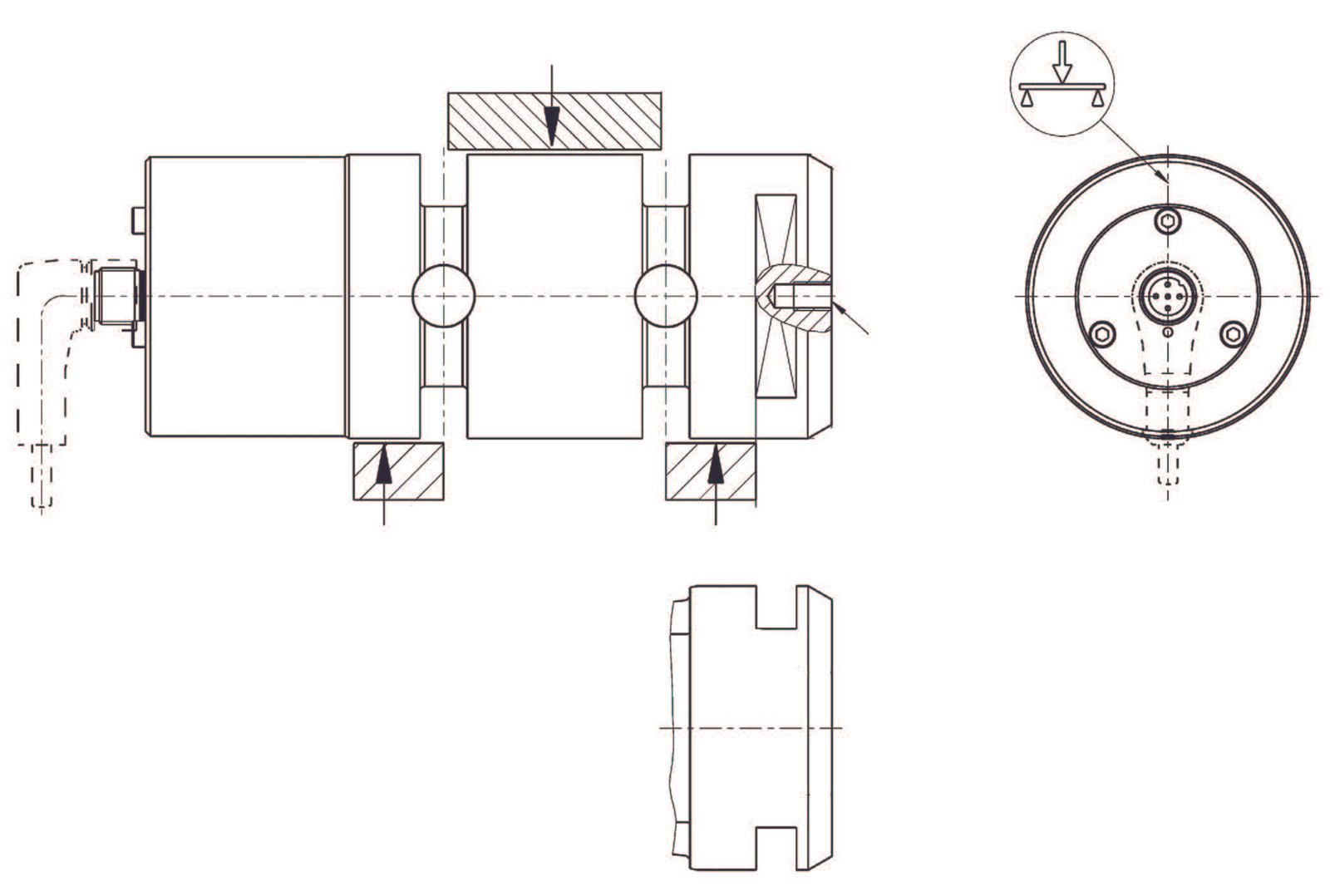
Dimensions in mm [in]
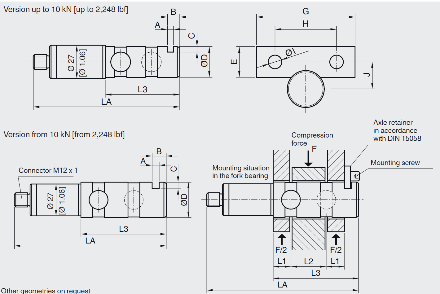
| Rated force in kN | Dimensions in mm | ||||||||||||
| LA | ØD 1) | L1 | L2 | L3 | A | B | C | E | G | H | ØI | J | |
| 5 | 115.5 | 20 | 10 | 20 | 50.5 | 5 | 10 | 4.0 | 20 | 60 | 36 | 9 | 16 |
| 10 | 125.5 | 25 | 12.5 | 25 | 60.5 | 5 | 10 | 4.5 | 20 | 60 | 36 | 9 | 18 |
| 20 | 135.5 | 30 | 15 | 30 | 72.5 | 6 | 12 | 5.5 | 25 | 80 | 50 | 11 | 22 |
| 30 | 145.5 | 35 | 17.5 | 35 | 82.5 | 6 | 12 | 6 | 25 | 80 | 50 | 11 | 24 |
| 50 | 160.5 | 40 | 22.5 | 40 | 97.5 | 6 | 12 | 6.5 | 25 | 80 | 50 | 11 | 26 |
| 100 | 175.5 | 50 | 23 | 50 | 112.5 | 8 | 16 | 7 | 30 | 100 | 70 | 13 | 33 |
| 200 | 223.5 | 70 | 35 | 70 | 160.5 | 10 | 20 | 10 | 40 | 140 | 100 | 17 | 45 |
| Rated force in lbf | Dimensions in Inch | ||||||||||||
| LA | ØD 1) | L1 | L2 | L3 | A | B | C | E | G | H | ØI | J | |
| 1,124 | 4.58 | 0.79 | 0.4 | 0.79 | 1.98 | 0.19 | 0.4 | 0.16 | 0.79 | 2.36 | 1.42 | 0.35 | 0.63 |
| 2,248 | 4.94 | 0.98 | 0.49 | 0.98 | 2.38 | 0.19 | 0.4 | 0.18 | 0.79 | 2.36 | 1.42 | 0.35 | 0.71 |
| 4,496 | 5.33 | 1.18 | 0.59 | 1.18 | 2.85 | 0.24 | 0.47 | 0.22 | 0.98 | 3.15 | 1.96 | 0.43 | 0.87 |
| 6,744 | 5.73 | 1.37 | 0.69 | 1.38 | 3.25 | 0.24 | 0.47 | 0.24 | 0.98 | 3.15 | 1.96 | 0.43 | 0.94 |
| 11,240 | 6.31 | 1.57 | 0.89 | 1.57 | 3.84 | 0.24 | 0.47 | 0.25 | 0.98 | 3.15 | 1.96 | 0.43 | 1.02 |
| 22,481 | 6.90 | 1.96 | 0.91 | 1.97 | 4.43 | 0.24 | 0.63 | 0.28 | 1.18 | 3.94 | 2.76 | 0.51 | 1.30 |
| 44,962 | 8.80 | 2.75 | 1.37 | 2.76 | 6.32 | 0.24 | 0.79 | 0.4 | 1.57 | 5.51 | 3.94 | 0.67 | 1.77 |
1) Bore/Bolt pairing: H9/f9
Mounting situation of the load pin
Pin retainer (in accordance with DIN 15058)
Dimensioning: The customer-specific load pin drawing of the respective order number has priority.
상품평
아직 상품평이 없습니다.