

설명
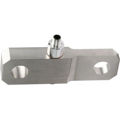
Models F7301, F73C1, F73S1 Tension link
With thin-film technology from 5 kN
Tension links are designed for static and dynamic measurement tasks in the direct flux of force. As a load-bearing component in existing constructions, they determine the tension forces in a wide scope of applications.
Tension links of these models are often used in hoist and crane systems as torque support or rope fix point for load measurements. Further application areas are special machine constructions, e. g. in polymer processing machines.
Appropriate technical and regional approvals are available as an option.
The tension links of the model F73x1 are either made of high-strength, corrosion-resistant stainless steel 1.4542 or robust fine-grained steel with surface protection. Due to their properties, these materials are particularly suitable for the applications of tension links.
As output signals, the common active current and voltage outputs are available (4 …. 20 mA, 0 … 10 V).
Redundant output signals and CANopen® protocols are also possible.
These force transducers can be integrated into a certified WIKA overload protection with model ELMS1 (DIN EN ISO 13849-1 with PL d/cat. 3).
Technical data in accordance with VDI/VDE/DKD 2638
| Models | F7301 and F73C1 with UL | F73S1 |
| Rated force Fnom kN [lbf] | ≥ 5 [≥ 1,124] | |
| Relative linearity error dlin 1) | ±0.5 % Fnom | |
| Relative repeatability error in unchanged mounting position brg | ±0.5 % Fnom | |
| Temperature effect on | ||
| characteristic value TKc | 0.2 % Fnom/10 K | |
| zero signal TK0 | 0.2 % Fnom/10 K | |
| Force limit FL | 150 % Fnom | |
| Breaking force FB | 300 % Fnom | |
| Shear force influence dQ (Signal with 100 % Fnom under 90°) 2) | ±2 % Fnom | |
| Rated displacement (typ.) snom | < 0.1 mm [< 0.004 in] | |
| Material of measuring device | ■ Corrosion-resistant stainless steel, 1.4542, ultrasound-tested 3,1 material ■ Version with 3,2 material available |
|
| Rated temperature BT, nom | -20 … +80 °C [-4 … +176 °F] | |
| Operating temperature BT, G | -30 … +80 °C [-22 … +176 °F] | -30 … +80 °C [-22 … +176 °F] |
| Storage temperature BT, S | -40 … +85 °C [-40 … +185 °F] | |
| Electrical connection | ■ Circular connector M 12 x 1, 4-pin or 5-pin ■ CANopen® Circular connector M 12 x 1, 5-pin ■ MIL connector |
■ 2-circular connector M 12×1, 4-pin ■ MIL connector |
| Output signal (rated output) Cnom | ■ 4 … 20 mA, 2-wire, ■ 4 … 20 mA, 3-wire ■ 2 x 4 … 20 mA, redundant ■ DC 0 … 10 V, 3-wire ■ DC 2 x 0 … 10 V redundant ■ Signal jump 4 … 16 mA, 2-wire 5) DC 2 … 8 V, 3-wire 5) ■ CANopen® Protocol in accordance with CiA®301, device profile CiA®404, communication services LSS (CiA®305), configuration of the instrument address and baud rate Sync/Async, Node/ Lifeguarding, heartbeat; zero and span ±10 % adjustable via entries in the object directory 3) |
Redundant opposing 4 … 20 mA/ 20 … 4 mA Version in accordance with requirements for functional safety per machinery directive 2006/42/EC as WIKA overload protection with model ELMS1 (DIN EN ISO 13849-1 with PL d/cat. 3). |
| Current consumption | ■ Current output 4 … 20 mA, 2-wire: signal current ■ Current output 4 … 20 mA, 3-wire: < 8 mA ■ Voltage output: < 8 mA ■ CANopen®: < 1 W |
Current output 4 … 20 mA, 2-wire: signal current |
| Supply voltage UB | ■ DC 9 … 36 V for current output ■ DC 13 … 36 V for voltage output ■ DC 9 … 36 V for CANopen® | DC 10 … 30 V for current output |
| Burden | ■ ≤ (UB – 10 V) / 0.024 A for current output ■ > 10 kΩ for voltage output |
■ ≤ (UB – 10 V) / 0.020 A (channel 1) for current output ■ ≤ (UB – 7 V) / 0.020 A (channel 2) for current output |
| Response time | ≤ 2 ms (within 10 … 90 % Fnom) 4) | |
| Protection (per EN/IEC 60529) | ||
| Unplugged condition | IP66, IP67 | IP67 |
| Plugged condition | IP68, IP69, IP69K | |
| Electrical protection | Reverse voltage, overvoltage and short-circuit protection | |
| Vibration resistance | 20 g, 100 h, 50…150 Hz (acc. to DIN EN 60068-2-6) | |
| Shock resistance | In accordance with DIN EN 60068-2-27 | |
| Immunity | ■ In accordance with DIN EN 61326-1/DIN EN 61326-2-3 ■ EMC-strengthened version |
|
1) Relative linearity error is specified in accordance with Directive VDI/VDE/DKD 2638 chapter 3.2.6
2) This value can result if 100 % Fnom acts at 90° to the axis.
3) Protocol in accordance with CiA®301, device profile CiA®404, communication service LSS (CiA®305)
4) Further reponse times possible on request.
5) Further signal jumps are realisable on request.
CANopen® and CiA® are registered community trademarks of CAN® in Automation e. V.
Technical data in accordance with VDI/VDE/DKD 2638
| Models | F73C1 ATEX/IECEx EX ib 1) |
| Rated force Fnom kN [lbf] | ≥ 5 [≥ 1,124] |
| Relative linearity error dlin 2) | ±0.5 % Fnom |
| Relative repeatability error in unchanged mounting position brg | ±0.5 % Fnom |
| Temperature effect on | |
| characteristic value TKc | 0.2 % Fnom/10 K |
| zero signal TK0 | 0.2 % Fnom/10 K |
| Force limit FL | 150 % Fnom |
| Breaking force FB | 300 % Fnom |
| Shear force influence dQ (Signal with 100% Fnom under 90°) 3) | ±2 % Fnom |
| Rated displacement (typ.) snom | < 0.1 mm [< 0.004 in] |
| Material of measuring device | ■ Corrosion-resistant stainless steel, 1.4542, ultrasound-tested 3,1 material ■ Version with 3,2 material available |
| Rated temperature BT, nom | -20 … +80 °C [-4 … +176 °F] |
| Operating temperature BT, G | Ex II 2G Ex ib IIC T4 Gb -25 °C < Tamb < +85 °C Ex II 2G Ex ib IIC T3 Gb -25 °C < Tamb < +100 °C Ex I M2 Ex ib I Mb -25 °C < Tamb < +85 °C Ex II 2G Ex ib IIC T4 Gb -40 °C < Tamb < +85 °C Ex I M2 Ex ib I Mb |
| Storage temperature BT, S | -40 … +85 °C [-40 … +185 °F] |
| Electrical connection | ■ Circular connector M 12×1, 4-pin ■ MIL connector ■ Cable gland |
| Output signal (rated output) Cnom | 4 … 20 mA, 2-wire |
| Current consumption | Current output 4 … 20 mA 2-wire: signal current |
| Supply voltage UB | DC 10 … 30 V for current output |
| Burden | ■ < (UB – 10 V) / 0,024 A for current output ■ > 10 kΩ for voltage output |
| Response time | ≤ 2 ms (within 10 … 90 % Fnom) 4) |
| Protection (acc. to EN/IEC 60529) | IP67 |
| Electrical protection | Reverse voltage, overvoltage and short-circuit protection |
| Shock resistance | 20 g, 100 h, 50…150 Hz acc. to DIN EN 60068-2-6 |
| Immunity | ■ In accordance with DIN EN 61326-1/DIN EN 61326-2-3 ■ EMC-strengthened version |
1) The load pin with ignition protection type “ib” should only be powered using galvanically isolated repeater power supplies.
Suitable repeater power supplies can be offered as an option, e.g. order number: 14255084.
2) Relative linearity error is specified in accordance with Directive VDI/VDE/DKD 2638 chapter 3.2.6.
3) This value can result if 100 % Fnom acts at 90° to the axis.
4) Further reponse times possible on request.
Dimensions/Mounting situation
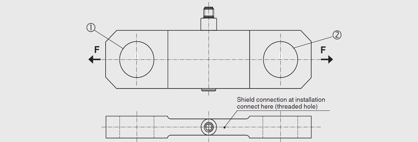
Dimensions: The customer-specific load pin drawing of the respective order number has priority.
Insert the corresponding bolts into the corresponding holes and on both sides. Load the tension link with tension force (F).

상품평
아직 상품평이 없습니다.