


설명
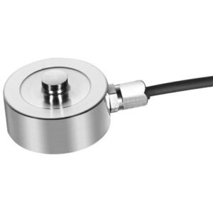
F241 Axial Compensated Loadcell
Geometry: Flexure strain assembly in cylindrical housing, open or weather sealed with end internal fixing. For universal use in tension and compression, with compensation for off axis load inputs.
The F241 is ideally suited to low range engineering force measurements and process weighing. When precision and easy installation are required various configurations allow the loadcell to be used in both tensile and compressive applications.
We are happy to design variants of this loadcell to meet your specific requirements. Versions can be manufactured for higher temperature operation. Please consult our engineering department.
Specification
| Parameter | Value | Unit |
|---|---|---|
| Non-linearity – Terminal | ±0.05 | % RL |
| Hysteresis | ±0.05 | % RL |
| Creep – 20 minutes | ±0.02 | % AL |
| Repeatability | ±0.02 | % RL |
| Rated output – Nominal | 2.2 | mV/V |
| Rated output – Rationalised | 2.0 | mV/V |
| Rationalisation tolerance (applies to single direction calibrations) | ±0.1 | % RL |
| Zero load output | ±4 | % RL |
| Temperature effect on rated output per °C | ±0.005 | % AL |
| Temperature effect on zero load output per °C | ±0.005 | % RL |
| Temperature range – Compensated | -10 to +50 | °C |
| Temperature range – Safe | -10 to +80 | °C |
| Excitation voltage – Recommended | 10 | V |
| Excitation voltage – Maximum | 10 | V |
| Bridge resistance | 350 | Ω |
| Insulation resistance – Minimum at 50Vdc | 500 | MΩ |
| Overload – Safe | 20 | % RL |
| Overload – Ultimate | 100 | % RL |
| Weight – Nominal (excluding cable) | 240 to 260 | g |
Order Codes
| Code | Description |
|---|---|
| F241CF00H0 | Compression, unrationalised |
| F241TF00H0 | Tension, unrationalised |
| F241UF00H0 | Bi-directional, unrationalised |
| F241CF00HN | Compression, rationalised |
| F241TF00HN | Tension, rationalised |
| F241UF00HN | Bi-directional, rationalised |
| Change the C to a D for compression with thread fitting. |
Structural Stiffness
| Range (kN) | Stiffness (N/m) |
|---|---|
| 30 | 1.5 x 10⁵ |
| 50 | 2.5 x 10⁵ |
| 100 | 5.0 x 10⁵ |
| 300 | 1.5 x 10⁶ |
Notes
- AL = Applied load.
- RL = Rated load.
- Temperature coefficients apply over the compensated range.
Connections
The loadcell is fitted with 2 metres of PVC insulated 4 core screened cable type 7-2-4C.
Excitation + = Red, Excitation – = Blue, Signal + = Yellow, Signal – = Green, Screen = Orange.
Reverse the signal connections to obtain a positive signal in tension mode. The screen is not connected to the loadcell body.
상품평
아직 상품평이 없습니다.